Date: 02 Feb 2011
Ampair ® 300 (Mk1, “Pacific”) Wind Turbine Manual
CD 2300
Issue: 1.2
Page 29 of 34
- 29 -
© Ampair, April 2007
Faulty rectifiers:
The rectifiers should last the life of the machine. The most likely cause for their demise
is accidental reverse polarity connection of Ampair to battery. If this is suspected the rectifier diode
bridges must be checked.
Diode Test:
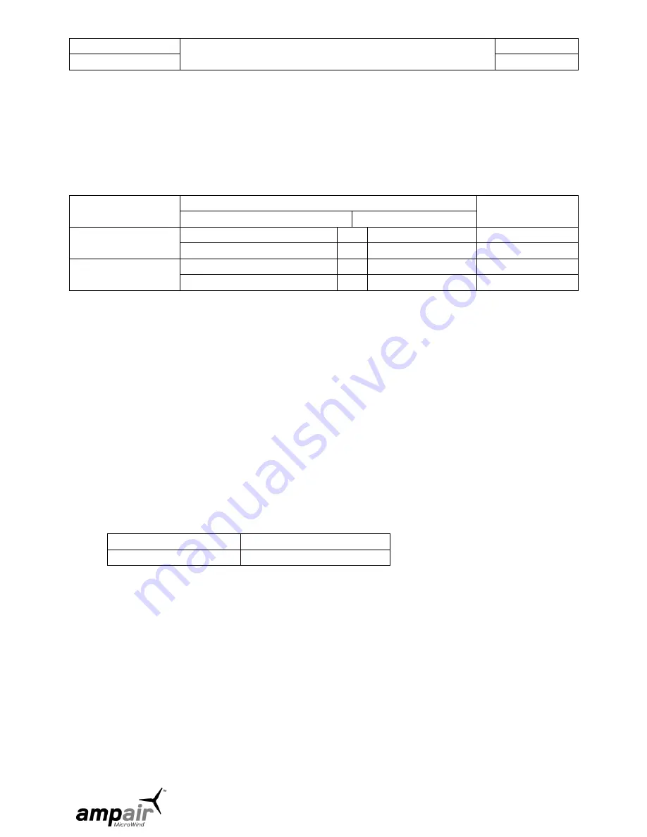
This test will show if the rectifier diodes are either open or short circuit. If your multimeter has
a diode check feature, select this (if not select the highest resistance range) and, after removing the
connecting wires apply the red meter lead to the red rectifier lead (disconnected from battery plus), black
meter lead to thick black lead (disconnected from battery minus), and note the reading. Now reverse the
connections.
METER LEAD
POSITION
MULTIMETER SETTING
CONCLUSION
DIODE TEST
OHMS x 100
Red to Red.
No reading
or
many Megohms
OK
Reading
or
low resistance
Not OK
Black to Red
0.5 to 1 volt (two diode drops)
or
markedly less*
OK
No reading
or
high resistance
Not OK
*This test is not as conclusive as the diode test method however, provided the first reading is a very high
resistance and the second reading far lower, then the test is valid. Actual values will depend on the
voltage supplied by the particular meter for its resistance ranges.
The rectifiers are located on a separate heat-sink which should have been installed near the regulator.
Unsolder the commoning links between the three rectifier outputs to check outputs separately.
6.1.1.4
Alternator section
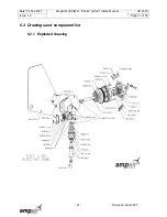
Referring to the exploded diagram of the wind turbine, undo the six M5 x 50 mm screws on the front of the
Ampair and pull the front fore-body flange away from the main body. Do this very carefully as it must be
withdrawn true or it will jam on the stator. The shaft and bearings are located using Loctite anaerobic
adhesives so some force may be necessary to part them. A puller may have to be improvised to do this.
This job should, therefore, be done on a suitable work bench. The rear bearing needs a bearing puller to
remove it, if no puller is available, a dummy shaft may be fixed in the bearing centre using epoxy adhesive
and, when cured, the bearing worked loose. The front bearing may be drifted out following removal of the
circlip. Prior to re-assembly, the bearing housings, the bearings inner and outer surfaces and the shaft
surfaces should all be thoroughly cleaned and de-greased.
When re-assembling use adhesives as follows:
Bearings to body
Loctite 641
Shaft to bearings
Loctite 641
When replacing the fore-body, make sure that the new "O" ring is in place and well smeared with silicone
grease. Assemble the body checking that the wiring to the stator cannot touch the rotor. Tighten the six
M5 x 50 mm bolts up slowly and evenly taking care to keep the stator parallel in the housing and tighten
until the body sealing O ring has been evenly compressed all the way around.
6.1.1.5
Stator and rotor replacement
This is normally a factory operation. Rotor damage is unlikely, but sometimes occurs due to corrosion or
other mechanical problems. Considerable force is necessary to break the adhesive bond between the
rotor and rotor shaft and a bearing press with guide tools to protect the shaft is needed. The magnets are
both very powerful and brittle, and so difficult to work with in the field. Rotor/shaft assemblies can be
returned for replacement.
Stator failure only normally occurs due to salt water immersion. Any accident causing this necessitates the
immediate cleaning of all parts with fresh water and then drying thoroughly. Leaving to dry naturally


