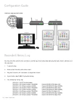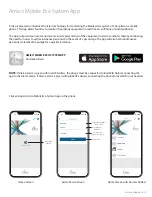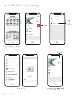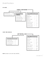
10 Amico Corporation
STEP 7: SENSOR MODULE
A: GAS DISPLAY (on screen location)
The location of gases displayed on screen is dependant upon which sensor channel each individual gas is connected to.
The display below indicates which sensor channel corresponds to each location the gas will be displayed on the LCD screen.
B: LOCAL (inside the back box)
i. The sensor module is provided with a 6" - 8" [0.1 m - 0.2 m] #22 gauge stranded,
shielded and twisted pair cable. One wire is red (positive) and the other wire is
black (negative). Connect the wires to the display module as shown in Appendix D.
Take the red wire from the sensor and attach it to terminal “” on the display
module. Take the black wire from the sensor and attach it to terminal “Sensor -”. The
terminal block on the display module is clearly marked for proper connection of the
sensor wires.
ii. Repeat the above procedures with the remaining sensor modules.
C: REMOTE (outside the back box)
i. The sensor module is provided with 6" - 8" [0.1m - 0.2m] #22 gauge stranded, shielded and twisted pair cable.
Connect the wires to a junction box (supplied by others) located near the sensor as per the wiring diagram
(see Appendix E).
ii. Connect a #22 gauge stranded, shielded and twisted pair cable ONLY, up to 2000 ft [609.6 m]. Knockouts are
provided throughout the alarm back box.
iii. Connect the red wire from the cable to the terminal on the display module marked ””. Connect the
black wire to terminal “Sensor -” as shown in the wiring diagram (see Appendix E).
iv. Repeat the above procedures with the remaining sensor modules using the wiring diagram.
NOTE:
• When remote sensors are used, ONLY a #22 gauge stranded, shielded twisted pair cable must be used (BELDEN
#8451 or equivalent, supplied by others).
• Do not ground the shield drain wire at sensor or inside the alarm panel back box
Installation Guide
1 Gas
2 Gases
3 Gases
4 Gases
5 Gases
6 Gases
7 Gases
8 Gases

