I-
STATUS MODULE
3. STATUS MODULE
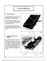
(a) Plug the connector at the end of the
tail of the Status module into the appro-
priate place on the motherboard.
(b) F l i p the status module so that it
hangs by its cable just below the box.
The circuit with all the components
should now be visible.
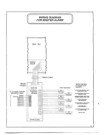
(c) Connect the external switches to
the appropriate terminal blocks on strip
J4 as per the wiring diagram shown on
page 11.
4. COMPUTER INTERFACE
MODULE
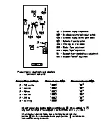
The computer interface module is a
piggyback board that fits on top of the
status module and plugs into connector
(P1) located at the top of the status
board. (Fig. 7) Plug the module in (if it
is not already on) and attach the board
using the five screws provided. Con-
nect the module to the computer inter-
face as shown in the wiring diagram on
page 13.
A
C O N N E C T O R P 1
T E R M I N A L B L O C K ( J 4 )
M O U N T I N G S C R E W S
Fig. 6

