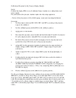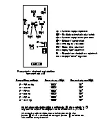
Calibration Procedure for the Pressure Display Module
Setup:
Connect the display PCB to a well calibrated Sensor module in a working frame and
power supply.
The calibration of the pressure module requires the following equipment:
- Source of known pressure with a reliable gauge or pressure measuring instrument.
Procedure:
1
Set the jumper selections SW1, SW2, SW3 and SW5 according to the pressure
range to be calibrated.
2
Set the calibrate/operate switch (SW4) to the calibrate position.
3
Apply power to the module.
4
Disconnect the pressure sensor module and short terminals #1 and #4 of connector
J2 on the display module. Adjust R22 for zero numerical indication.
5
Reconnect the pressure sensor module and apply a known, measured pressure
(preferable at least 90% full scale) to the pressure transducer.
6
Adjust R25 for the appropriate numerical indication for the range and units of
display settings of SW1, SW2, SW3 and SW5. Repeat steps 4,5 and 6 until
satisfactory.
7
Apply an input for 50% of scale. Adjust R42 to place the bargraph display at
center.
8
Confirm that the decimal select jumper SW3 will turn on either the middle or
right hand decimal points.
9
Confirm that alarms are generated and that the "HI ALARM" and "LOW
ALARM" LED's flash and the "NORMAL" LED extinguishes, by changing the
pressure out of the safe area (+/- 20%), or by readjusting R42 to artificially move
the LED bar display.
10
Put the calibrate/operate switch (SW4) to the operate position.
The Pressure Display Module is factory calibrated for set points at 40 PSI (LOW)/60 PSI
(HIGH). If you wish to change the settings, you would adjust "R42" to move the whole
range up or down. DO NOT adjust "R22" and "R25", they are factory set at "0" and full
scale. Do not adjust the potentiometers on the sensor modules, they are also factory set at
"0" and full scale. To obtain a larger or smaller range you must change "SW2" and then
adjust "R6" to obtain the proper range. You would then adjust "R42" to obtain the desired
values.
Calibration Procedure for the Pressure Display Module
Setup:
Connect the display PCB to a well calibrated Sensor module in a working frame and
power supply.
The calibration of the pressure module requires the following equipment:
- Source of known pressure with a reliable gauge or pressure measuring instrument.
Procedure:
1 S e t the jumper selections SW1, SW2, SW3 and SW5 according to the pressure
range to be calibrated.
2 S e t the calibrate/operate switch (SW4) to the calibrate position.
3 A p p l y power to the module.
4 D i s c o n n e c t the pressure sensor module and short terminals #1 and #4 of connector
J2 on the display module. Adjust R22 for zero numerical indication.
5 R e c o n n e c t the pressure sensor module and apply a known, measured pressure
(preferable at least 90% full scale) to the pressure transducer.
6 A d j u s t R25 for the appropriate numerical indication for the range and units of
display settings of SW1, SW2, SW3 and SW5. Repeat steps 4,5 and 6 until
satisfactory.
7 A p p l y an input for 50% of scale. Adjust R42 to place the bargraph display at
center.
8 C o n f i r m that the decimal select jumper SW3 will turn on either the middle or
right hand decimal points.
9 C o n f i r m that alarms are generated and that the "HI ALARM" and "LOW
ALARM" LED's flash and the "NORMAL" LED extinguishes, by changing the
pressure out of the safe area (+/- 20%), or by readjusting R42 to artificially move
the LED bar display.
10 P u t the calibrate/operate switch (SW4) to the operate position.
The Pressure Display Module is factory calibrated for set points at 40 PSI (LOW)/60 PSI
(HIGH). If you wish to change the settings, you would adjust "R42" to move the whole
range up or down. DO NOT adjust "R22" and "R25", they are factory set at "0" and full
scale. Do not adjust the potentiometers on the sensor modules, they are also factory set at
"0" and full scale. To obtain a larger or smaller range you must change "SW2" and then
adjust "R6" to obtain the proper range. You would then adjust "R42" to obtain the desired
values.


