30
durability
,
please use
Hydraulic Oil 46#
).
2.
Press the control button, the cables will be strained. Check whether the cables
match the pulley. Make sure the cables are not across.
3.
Press the release valve handle to lock the cross-beam to the safety ladders, and
then adjust the platforms to be level by adjusting the nuts of safety ladders.
4.
Adjust the cable fitting hex nuts to make platforms and four safety locks work
synchronously. You need to run the lift up and down for several times, meanwhile
do the synchronous adjustment till the four safety devices can lock and release at
the same time.
5.
Adjust the clearance between the column and the plastic slider of cross-beam to
about 2mm, Do not tighten the bolts of the sliding block, let the sliding block can
be
turned after installing the bolts
6.
After finishing the above adjustment, test running the lift with load. Run the lift
with platforms in low position first, make sure the platforms can rise and lower
synchronously and the safety device can lock and release synchronously. And then
test run the lift to the top completely. If there are anything improper, repeat the
above adjustment.
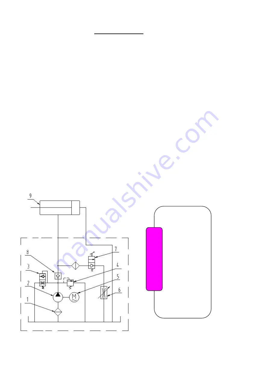
Circuit Diagram of Hydraulic System
VI. OPERATION INSTRUCTIONS
Fig. 42
1. Filter
2. Gear pump
3.Cushion valve
4. Relief Valve
5. Motor
6. Throttle Valve
7.
Release Valve
8. Check valve
9. Cylinder For
Four-post lift
N
O
T
E


