


21
a. The source wires (
L1, L2, L3
) are connected with terminals of AC contactor marked
L1, L2, L3
respectively.
b. Terminals
4#
of control button is connected with terminals of AC contactor marked
L1
; wire
3#
is connected with
A1
terminals of control button.
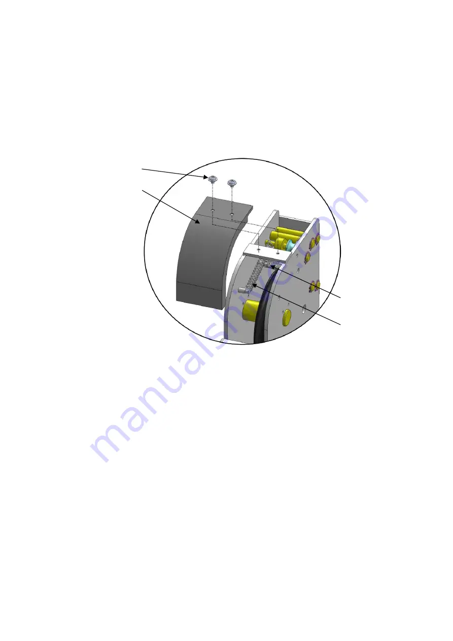
M. Install spring and safety cover of cross beam
(See Fig. 28).
N. Install drive-in ramp, jack tray and plastic oil pans
(See Fig. 29)
.
59
57
58
60
Fig. 28


