background image

Instruction Manual

Page 1

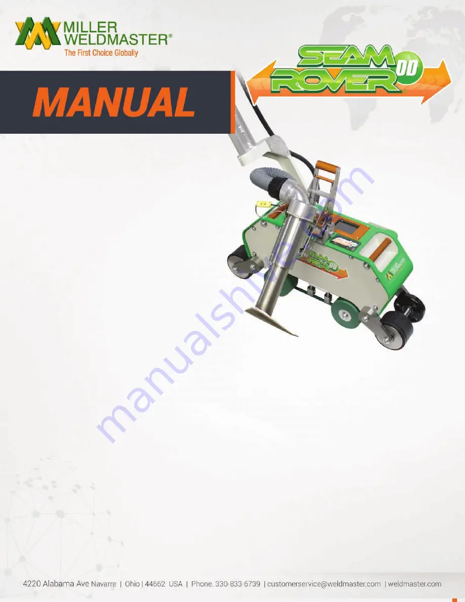
This instruction manual is intended to be a guide when operating the Seamrover DD. To ensure optimal 

performance from your welder, please follow the recommendations and specifications precisely. 


You can also subscribe to Miller Weldmaster Insiders to stay updated on tech tips, machine maintenance 

updates, and more at www.weldmaster.com/insiders.

Summary of Contents for Seamrover DD

Page 1: ...erating the Seamrover DD To ensure optimal performance from your welder please follow the recommendations and specifications precisely You can also subscribe to Miller Weldmaster Insiders to stay updated on tech tips machine maintenance updates and more at www weldmaster com insiders ...

Page 2: ...pter 5 GPS Tracking and Data Logging System Chapter 6 Definition of Controls Chapter 7 Recommended Replacement Parts Chapter 8 Machine Specifications Chapter 9 Maintenance Chapter 10 Transportation Specs and Storage Chapter 11 Technical Requirements Chapter 12 Training Page 3 Pages 4 Page 5 Page 5 Page 6 Page 7 8 Pages 9 Pages 10 Page 11 16 Page 16 Page 16 Page 17 Table of Contents ...

Page 3: ... The manufacturer does not approve of Any other uses for these machines The removal of any safety guards while in operation Unauthorized modification of the machines Using replacement parts that are not manufacturer approved Only a properly trained technician may operate and or perform any routine maintenance or repairs to the machines NOTE The manufacturer will not be held liable for any damage o...

Page 4: ...machine should always have the power disconnected before the cover is open Caution Electricity This is a high voltage machine and proper precautions should be taken during operation and servicing Caution Hot Areas near the nozzle are hazardous and unsafe to touch Warning Keep Hands Clear To prevent any pinching or burns be aware of the loca tion of your hands at all times Warning High Temperature ...

Page 5: ...umps air over the heating element and carries the heat through the Hot Air Nozzle applying the heat to the material to be welded The hot air temperature ranges from 100 to 1350 Degrees Fahrenheit 25 to 730 Degrees Celsius Speed The Speed of the Weld Rollers determines the amount of time the heat is applied to the material being welded The slower the speed setting the more the material will be heat...

Page 6: ...Instruction Manual Page 6 CHAPTER 5 GPS Tracking and Data Logging System Page 6 ...

Page 7: ...ne 0 15 Available recipe settings Machine Speed This is the speed of the Weld Roller The speed can be adjusted by spinning the control knob Each detent of the knob increases or decreases the speed by 1ft min Actual Temperature This is how hot the machine is currently Temperature Set Point This is how hot you want the machine to be for the purpose of welding your thermal plastics 6 0 Definition of ...

Page 8: ...nto position the Drive Start Delay Time will delay the weld rollers from turning until the set point is reached The Drive Start Delay Time will be adjusted by the operator to the desired setting Language Select the language according to demand MAX Output 1350 F 32ft min 50 100 blower Hour Meter The hour meter will count total time of which the heating system is on Presets When changing parameters ...

Page 9: ...REPLACEMENT PARTS 7 0 Recommended Replacement Parts Miller Weldmaster recommends keeping the following spare parts in stock NOTE The manufacturer will not be held liable for any damage or injuries occurring from any inappropriate use of this machine ...

Page 10: ...30volt Rated Power 4600 W Rated Voltage 230v AC 50 60hz Maximum Temperature 1350 F 730 C Machine Speed 1 32 ft min Overall Dimensions 27 x 14 x 13 Seam Width up to 2 Net Weight 88lbs Operator Controls Section Control Panel The HMI Human Machine Interface Digital Screen allows you to set system controls Power On Off Switch Power switch turns the machine on and off Other Power Supply Outboard Fuses ...

Page 11: ...nect the power from the machine before proceeding Nozzle Position Horizontal To adjust horizontal nozzle position loosen the four flat head bolts located on the nozzle mounting bracket When all four bolts are slightly loose slide the nozzle into place while applying downward pressure on the nozzle mounting bracket Once the nozzle placement is satisfactory tighten the bolts in a crisscross pattern ...

Page 12: ...satisfactory tight en the jam nut Fine tune the vertical nozzle position such that the nozzle can easily swing into the seam to be welded 9 0 Maintenance Thermocouple Replace the thermocouple by removing the four socket head cap screws on the side of the element housing This allows removal of the thermocouple guard Break the thermocouple free using a wrench Cut and remove the protective heat shrin...

Page 13: ...element housing cap Slowly pull the cap directly out of the element housing Remove the element insulat ing tube and the element housing cap gasket and set aside Now the element can be unplugged from the element housing cap Installation is reverse of removal 9 0 Maintenance Step 1 Step 2 Step 3 Step 4 Step 5 CHAPTER 9 MAINTENANCE ...

Page 14: ...avoid damaging the control module Display and Operating Panel never plug or unplug the cables connecting the PLC Display and Operating Panel while the power is on 3 If there is any fault that cannot be removed please immediately contact the service department at Industrial Heat Sources IHS at 1 330 970 9353 Drive System 1 Check if the Driving Sprockets are dislocated or loosened 2 Check if the cha...

Page 15: ...ance item chains should be inspected once a year to ensure there is not excessive corrosion rust or dirt Also inspect for any looseness or slack If needed lubricate chains once a year with 80w 90w gear oil 1 Turn the circuit breaker to the off position 2 Disconnect the power cord from the power supply 3 Tilt the machine on it s side and inspect the chains Perform any maintenance to the chains as n...

Page 16: ... the machine to be alert to the potentially hazardous areas on the machine NOTE The manufacturer will not be held liable for any damage or injuries occurring from any inappropriate use of this machine Technical Requirements 1 When the Weld Rollers are aligned properly the edges of the two rollers should be parallel and aligned 2 Heat System Swing The swing in out of the heat system should be smoot...

Page 17: ...Instruction Manual Page 17 12 0 Training CHAPTER 12 TRAINING ...

Page 18: ..._____________________________________________ _______________________________________________________________________ _______________________________________________________________________ ______________________________________________________________________ _______________________________________________________________________ ___________________________________________________________________...

Page 19: ..._______________________________________ _______________________________________________________________________ _______________________________________________________________________ ______________________________________________________________________ _______________________________________________________________________ _______________________________________________________________________ _...

Page 20: ..._____________________________________________ _______________________________________________________________________ _______________________________________________________________________ ______________________________________________________________________ _______________________________________________________________________ ___________________________________________________________________...

Reviews: