0548-990/52g
2019.10
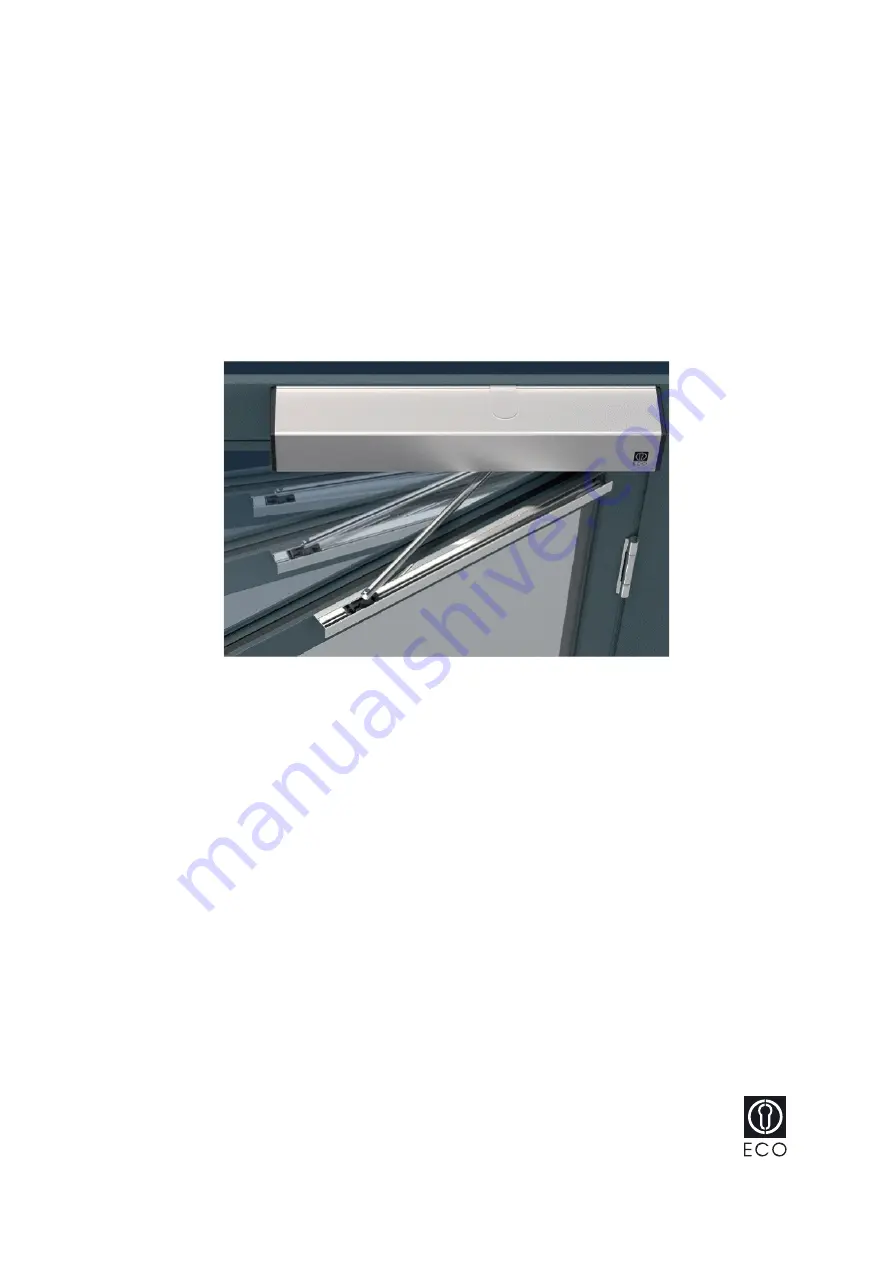
Swing door drive mechanism
ETS 73
Mounting and operating instructions
Original
Com. no.
.................................................. Pos. ................................. Construction year ...................
Operator
............................................................................................................................................................
Operating place ........................................................................................................................................................