background image

KEEP FOR FUTURE REFERENCE 


INSTRUCTIONS 

International Version 

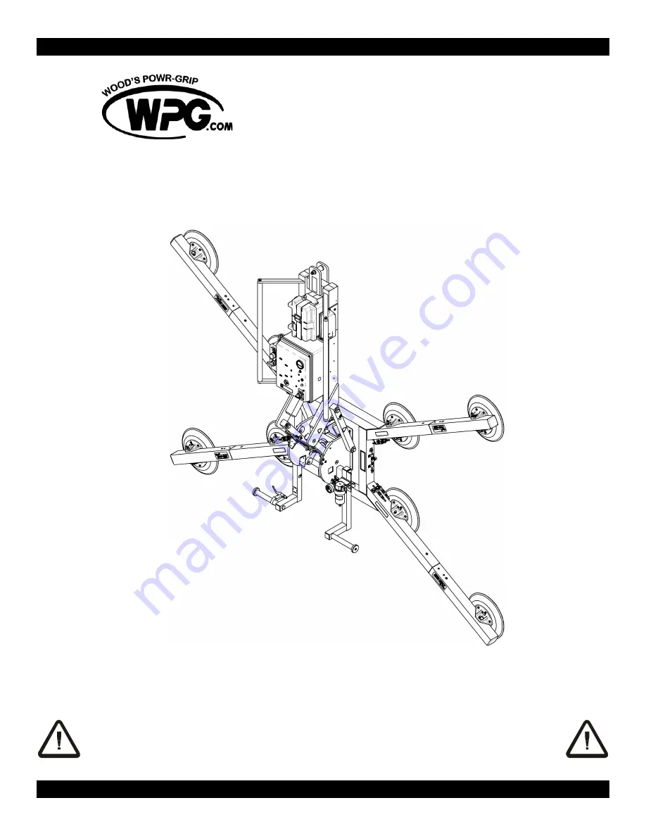
MODEL NUMBERS:   MRTARC8HV11DC, 

MRTARC811LDC 

SERIAL NUMBER:   ___________ 

(please see serial label and record number here) 


QUADRA-TILT ROTATOR 

DC-VOLTAGE, HIGH-FLOW, WITH PENDANT 


READ ALL INSTRUCTIONS AND WARNINGS 

BEFORE OPERATING THIS LIFTER


DESIGNED FOR THE MATERIALS HANDLING PROFESSIONAL 


P.O. Box 368 – 908 West Main 

Laurel, MT  USA  59044 

phone  800-548-7341 

phone  406-628-8231 

fax  406-628-8354 

Summary of Contents for MRTARC811LDC

Page 1: ..._______ please see serial label and record number here QUADRA TILT ROTATOR DC VOLTAGE HIGH FLOW WITH PENDANT READ ALL INSTRUCTIONS AND WARNINGS BEFORE OPERATING THIS LIFTER DESIGNED FOR THE MATERIALS HANDLING PROFESSIONAL P O Box 368 908 West Main Laurel MT USA 59044 phone 800 548 7341 phone 406 628 8231 fax 406 628 8354 ...

Page 2: ......

Page 3: ...ests 14 Confirming the Pad Frame Configuration 15 Preparing to Use the Optional Remote Control System 15 TO APPLY THE PADS TO A LOAD 16 Powering up the Lifter 16 Positioning the Lifter on the Load 16 Sealing the Pads against the Load 17 Reading the Vacuum Gauge 17 Vacuum Level on Optimal Surfaces 18 Vacuum Level on Other Surfaces 18 TO LIFT AND MOVE THE LOAD 19 About the Tilt Linkage 19 About the ...

Page 4: ... AIR FILTER MAINTENANCE LARGE 32 Filter Function and Conditions Requiring Service 32 Filter Service Procedures 32 VACUUM PUMP MAINTENANCE THOMAS 2907CDC22 12 33 Replacing a Diaphragm 1 33 Replacing an Intake Valve Flapper 6 33 Replacing a Set of Exhaust Valve Flappers 9 10 and a Head Gasket 12 33 VACUUM PUMP MAINTENANCE DYNAFLO DV1032102 34 Replacing the Diaphragm 34 Replacing the Gasket Flap Valv...

Page 5: ...r vacuum level is sufficient for lifting maximum load weight higher than 16 Hg 54 kPa Low Vacuum Warning Buzzer Maximum Alarm Volume 103 dBA at 2 ft 60 cm While the lifter is powered up an audible alarm warns the operator whenever vacuum is not sufficient for lifting the maximum load weight Options Available with Model LB8TLO Tilt Lock When engaged this option ensures that the upright or flat orie...

Page 6: ... Always position the vacuum pads correctly on the load prior to lifting see OPERATION TO APPLY THE PADS TO A LOAD Never lift a load when any vacuum indicator shows inadequate vacuum Never touch the vacuum release controls during a lift This may result in loss of vacuum and release of the load Never allow people to ride on the lifter or the load being lifted Never lift a load higher than necessary ...

Page 7: ...nd movable control pendant 1 LIFT SPOOL 9 VACUUM GAUGE 18 VACUUM LIFT LIGHT 2 LIFT BAR 10 AIR FILTER 19 MOVABLE CONTROL PENDANT 3 BATTERY CHARGER 11 CONTROL HANDLE 20 CONTROL HANDLE 4 BATTERY GAUGE 12 ROTATION RELEASE LEVER 21 Enclosure with VACUUM PUMP S 5 BATTERY TEST BUTTON 13 MOVABLE PAD MOUNTS VACUUM SWITCH and 6 POWER SWITCH 14 VACUUM PAD LOW VACUUM WARNING BUZZER 7 EXTENSION ARM 15 QUICK CO...

Page 8: ...4 VACUUM LIFT LIGHT 5 LOW VACUUM WARNING BUZZER 6 ENABLE BUTTON 7 APPLY BUTTON 8 RELEASE BUTTON 1 TRANSMISSION INDICATOR LIGHT 2 TRANSMITTER POWER ENABLE BUTTON 3 RELEASE BUTTONS 4 APPLY BUTTONS 5 EMERGENCY TRANSMITTER DISCONNECT OPTIONAL RADIO TRANSMITTER OPTIONAL REMOTE CONTROL SYSTEM ...

Page 9: ...he lift spool Note Some hoisting equipment hooks could interfere with an upright load that extends beyond the lifter s pad frame If the load would contact the hook during lifter operation the operator must prevent this by attaching a sling or other rigging that does not interfere with the load between the hook and the lift spool WARNING Any sling used must be rated to carry maximum load weight plu...

Page 10: ... following illustrations show several possible configurations Select a configuration to provide optimal support across the load surface and to minimize load overhang see OPERATION BEFORE USING THE LIFTER Note Smaller dimensions indicate Pad Spread when extension arms are removed see To Install Remove Extension Arms to follow Shaded circles indicate alternative locations of vacuum pads see To Repos...

Page 11: ... pad reduces lifter s load capacity To calculate the load capacity when some vacuum pads are disconnected consult the Per Pad Load Capacity see SPECIFICATIONS and multiply by the number of pads currently in use Make sure all vacuum hoses are secure and routed to avoid being pinched snagged abraded or otherwise damaged while the lifter is in operation WARNING Make sure all vacuum hoses are coiled o...

Page 12: ... maximum structural capacity of 350 lbs 159 kg To Install Remove Extension Arms 1 Remove the cotterless hitch pin from one extension arm 2 Insert the end of the extension arm in its socket on the pad frame so that the holes align for the cotterless hitch pin 3 Secure the extension arm in the pad frame by pushing the cotterless hitch pin through the holes until the retaining ball emerges on the far...

Page 13: ...h of the load are determined by the Pad Spread see SPECIFICATIONS the maximum length and width are determined by the allowable overhang or the amount of load material that can extend sideways beyond the vacuum pads without breaking or otherwise being damaged The allowable overhang depends on the kind of load material being lifted the thickness of the material and the angle at which it is handled i...

Page 14: ...ATIONS The lifter s work environment must be free of metal particles or any other contaminates that could damage lifter components through airborne contact or any other means of transmission in the environment If such contaminates cause a vacuum pump failure they could result in a load release and possible injury to the operator or others nearby WARNING Environmental contaminates could result in v...

Page 15: ...fter has reached the end of its service life you must dispose of the lifter in compliance with all local codes and regulatory standards that are relevant for the geographical region Note This lifter is equipped with a battery which may be subject to special disposal regulations ...

Page 16: ...TENANCE BATTERY TEST Perform all inspections and tests required by the INSPECTION and TESTING SCHEDULES see MAINTENANCE In addition if the lifter has been in storage always conduct a VACUUM TEST before placing it in service see MAINTENANCE CAUTION Examine each air filter regularly and empty when necessary The lifter is equipped with one or more air filters to help protect the vacuum system from co...

Page 17: ...ded there is a direct and clear view of the lifter and its status indicators from the operator location see MAINTENANCE REMOTE CONTROL SYSTEM TEST When lifting a load from a remote location the operator must monitor the lifter at all times to make sure that it is functioning as intended 6 In addition the operator must exercise special care to ensure that the load is landed and supported correctly ...

Page 18: ... unexpectedly see TO LIFT AND MOVE THE LOAD About the Tilt Linkage and TO ROTATE THE LOAD EDGEWISE to follow and it may also damage the lifter 9 Make sure that all vacuum pads will fit entirely on the load s contact surface see SPECIFICATIONS Pad Spread and that they will be loaded evenly while lifting see SPECIFICATIONS Per Pad Load Capacity Then position the lifter on the load so that all pads a...

Page 19: ...is energizes the vacuum pumps causing air to be drawn immediately at the vacuum pads The low vacuum warning buzzer also sounds an alarm until the lifter attains sufficient vacuum to lift the maximum load weight see TO LIFT AND MOVE THE LOAD Load Capacity and Lift Light to follow Press the lifter onto the load until all the pads seal against it The lifter must remain in the apply mode throughout th...

Page 20: ... load If the load has rough or porous surfaces the operator must conduct a test to determine whether the lifter is designed to lift the load as follows 1 Make sure the lifter s vacuum generating system is functioning correctly see MAINTENANCE VACUUM TEST 2 Apply the vacuum pads to the load as previously directed 3 After the vacuum pump stops running place the power switch in the off position 4 Rai...

Page 21: ...DS TO A LOAD preceding CAUTION Failure to load lifter correctly may damage tilt lock or other lifter components The tilt lock can be set to engage automatically when the pad frame reaches the vertical or horizontal position or it can be deactivated depending on the application To Use the Tilt Lock To allow automatic locking make sure the lock handle catch plate assembly 1 is set to slide up and lo...

Page 22: ...um level is lower than 16 Hg 54 kPa Discontinue lifter use until the cause of the vacuum loss can be determined If the pump runs at intervals of ten minutes or less while the lifter is attached to clean smooth nonporous materials the leakage is likely to be in the vacuum system In this event perform the VACUUM TEST see MAINTENANCE and inspect the vacuum pads for damage see MAINTENANCE VACUUM PAD M...

Page 23: ...igned to support the load for at least 5 minutes without power this depends on many factors including the condition of the load and the lifter s vacuum system see INTENDED USE LOAD CHARACTERISTICS and MAINTENANCE VACUUM PAD MAINTENANCE VACUUM TEST If a power failure occurs keep all personnel clear of the suspended load until it can safely be placed on the ground or a stable support Correct any def...

Page 24: ...sure it is either disengaged or locked out see OPERATION TO LIFT AND MOVE THE LOAD About the Optional Tilt Lock Then lift upward or press downward on the lower control handles to tilt the load as desired Since the tilt linkage is designed to automatically maintain the load in either the upright or the flat position the load force on the control handles changes direction during the tilt If load siz...

Page 25: ...ckly breaking the vacuum seal Continue to hold both buttons until the vacuum pads disengage completely from the load If the lifter is equipped with a Remote Control System a strobe light flashes as long as the operator is pressing the enable or release buttons This serves to show the operator when signals are being transmitted successfully from a remote location and also to warn other personnel th...

Page 26: ...oring the Lifter Use the covers supplied to keep the vacuum pads clean CE In accordance with CE Standard EN 13155 the lifter is designed to rest on relatively horizontal surfaces without tipping over To store the lifter in this way set the lifter with the pads facing downward on a clean smooth flat surface Then lower the lift bar to a horizontal orientation and place a support under the lift spool...

Page 27: ... hours use or whenever lifter is out of service for 1 month or more Examine the lifter s structure for visual damage Examine the vacuum system including vacuum pads fittings and hoses for visual damage Examine the air filter for conditions requiring service see AIR FILTER MAINTENANCE to follow Perform the VACUUM TEST to follow Check for unusual vibrations or noises while operating the lifter If th...

Page 28: ...100 of its Maximum Load Capacity see SPECIFICATIONS using an actual load or an equivalent simulation 13 Employ the following method to test with an actual load 1 Place a test load with appropriate LOAD CHARACTERISTICS see INTENDED USE on a stable support Make sure the load is oriented in the upright position 14 2 Apply the vacuum pads to the load as previously directed 3 After the vacuum pump stop...

Page 29: ...s lower than 50 of capacity While the lifter s power switch is in the on position and the vacuum system is in stand by mode see OPERATION TO RELEASE THE PADS FROM THE LOAD the operator must press the battery test button for a few moments to make the energy level register on the battery gauge This enables the operator to check the battery energy while the lifter is powered up but not attached to a ...

Page 30: ...ght on the battery gauge also turns on to indicate that the battery is fully charged Be sure to unplug the charger and check the battery energy again before operating the lifter see BATTERY TEST preceding When the lifter and its charger are used as directed the battery should take no more than 8 hours to charge completely 18 However following long term use a battery gradually loses the capacity to...

Page 31: ...ciency before using the lifter Contaminates on the pad face or sealing edges Soil build up can prevent pads from sealing adequately or reduce the friction coefficient see discussion preceding Follow the directions to clean pads as necessary see discussion to follow Filter screen missing from pad face This screen helps prevent debris from plugging the vacuum hose and the air filter Replace any miss...

Page 32: ...oth nonporous surface The surface should be flat or possess no more curvature than the lifter is designed for if any 20 When the pumping cycle is completed the vacuum level should register above 16 Hg 54 kPa on the vacuum gauge if not see VACUUM SWITCH ADJUSTMENT to follow 3 After the vacuum pump stops running leave the pads attached to the surface and place the power switch located on the lifter ...

Page 33: ...ace any expended battery see REPLACEMENT PARTS LIST Metal or other electrically conductive surfaces may be causing interference between the radio transmitter and radio receiver Although the transmission signals often can bounce around interfering surfaces the signals do not travel through conductive walls Reposition the transmitter as necessary to transmit signals effectively If the preceding dire...

Page 34: ...d bowl seal 5 with mild soap and water and skip to step 7 3 Unscrew the baffle 4 and remove the element and deflector 2 4 Discard the element and the bowl seal 5 5 Clean all internal parts and the bowl using mild soap and water only Do not use any other cleaners 6 Install the deflector and a new filter element then screw the baffle back on tighten gently finger tight to hold the element in place 7...

Page 35: ...t of Exhaust Valve Flappers 9 10 and a Head Gasket 12 1 Remove the six head screws 14 and remove the head 13 2 Turn the head upside down and remove the five valve plate screws 7 3 Lift out the valve plate 8 to access the exhaust valve flappers 9 10 and head gasket 12 22 4 Remove the exhaust valve flapper screw 11 and replace the exhaust valve flappers 5 Replace the head gasket and reverse the abov...

Page 36: ...in the illustration Replacing the Gasket Flap Valves 1 Remove the four head screws 1 and lock washers 2 and remove the head assembly 3 7 2 Invert the head and remove the two valve plate screws 7 Remove the valve plate 6 to access the gasket flap valves 3 Replace the gasket flap valves 5 and reverse the steps above for reassembly as shown in the illustration Use the alignment pin 15 to ensure prope...

Page 37: ...to lift the maximum load weight If the pump does not turn off and the lift light does not turn on after vacuum increases to a level much higher than the minimum lifting level the vacuum switch may be adjusted to maintain a lower vacuum level Otherwise the pump would continue to run unnecessarily after the lifter has attained sufficient vacuum to lift the maximum load weight If the pump does not tu...

Page 38: ...g vacuum switch from end with electrical connectors 2 Recheck the vacuum switch setting following each 1 6th turn of the adjustment screw In order to test the adjustment accurately release the vacuum pads completely before reapplying them to a test surface When the vacuum switch is adjusted correctly the vacuum pump turns off only after vacuum increases to a level higher than the minimum lifting l...

Page 39: ...4 Pad Spring Wave Type for HV11 pad 8 65010 Pad Spring Coil Type for G3370 pad 8 64752 Audio Alarm 5 15 V DC Panel Mount 1 64713AM Battery Charger 240 V AC Australian Type 1 64712AM Battery Charger 100 120 V AC 1 64711AM Battery Charger 240 V AC 1 64682 Battery 1 5 V DC AA Alkaline for optional radio transmitter 2 64667 Battery 12 V DC 26 Amp Hours 1 64590 Battery Gauge 1 64464 Circuit Breaker 30 ...

Page 40: ...16057 Quick Connector 1 8 FNPS Male End 8 16056 Quick Connector 1 8 FNPS Female End 8 15910 Vacuum Gauge 1 8 NPT CBM 1 15650 360 Rotating Union 1 4 NPT 1 15630 Pad Filter Screen Large 8 13532 Cotterless Hitch Pin 1 2 13 mm Dia x 5 127 mm Length 12 11726AM Clamp Collar 2 157 18 Thread 1 Piece 1 10900 Shoulder Bolt Socket Head 5 16 X 1 2 X 1 4 20 Thread for mounting pads 48 SERVICE ONLY WITH IDENTIC...

Page 41: ... use Repairs are required due to abnormal wear and tear The product has been damaged misused or neglected If a problem is not covered under warranty Powr Grip will notify the customer of costs prior to repair If the customer agrees to pay all repair costs and to receive the repaired product on a C O D basis Powr Grip then will proceed with repairs Wood s Powr Grip Co Inc 908 West Main St P O Box 3...

Page 42: ...Rev 5 2 9 16 40 MRTARC8 DC 35076RC ...

Page 43: ...Rev 5 2 9 16 41 MRTARC8 DC 35076RC ...

Page 44: ...Rev 5 2 9 16 42 MRTARC8 DC 35076RC ...

Page 45: ...Rev 5 2 9 16 43 MRTARC8 DC 35076RC ...

Page 46: ...Rev 5 2 9 16 44 MRTARC8 DC 35076RC ...

Reviews: