Ametek OXYvisor Installation, Operation & Maintenance Manual Download Page 69

69

Installation, Operation & Maintenance Manual

OXYvisor Optical Oxygen Analyzer

Installation of the Junction Box:
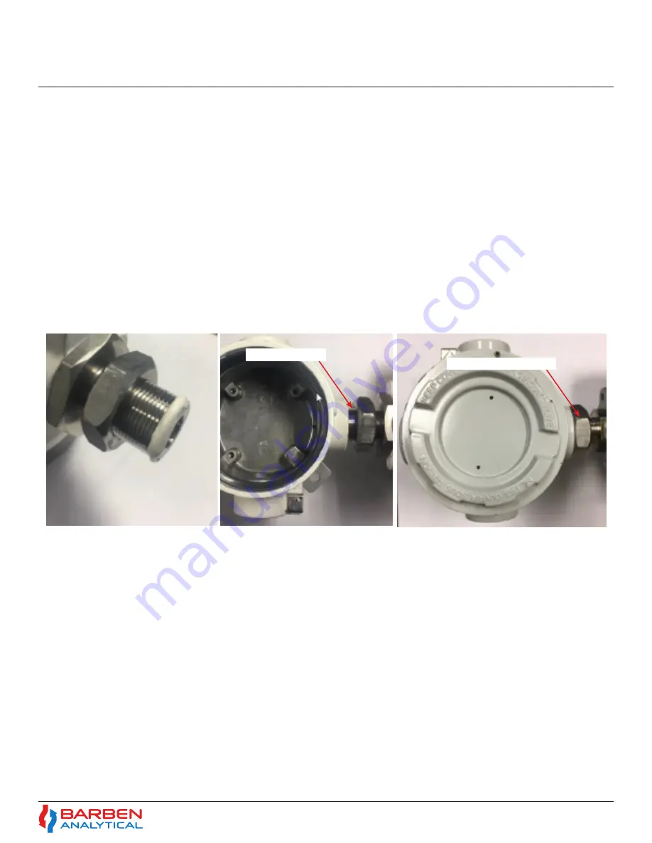
1.  Put the jam nut (B4711-1004) about 2/3 of the distance onto the exposed bushing threads.  Apply a small 

bead of Loctite 577 (B8008-1014) thread sealant to the first two threads on the bushing around the full 

perimeter.  A finger may be used to smear the sealant to fully cover the first two threads.

2. 

Carefully thread the junction box onto the bushing without damaging the fiber optic cable or the RTD cable, 

if applicable.  If a sensor wand is used, fully extend the wand and gently thread it through the junction 

box M24 hole and opposite 1/2” NPT hole.  Screw the Junction Box onto the bushing with 5 to 7 full turns.  

Leave the junction box opening facing the same direction as the opening of the big compartment on the 

main enclosure.  Apply a small drop of Loctite 577 thread sealant, or use excess from previous, to the first 

couple of exposed threads beyond the junction box interface.  Secure the jam nut to the junction box and 

tighten to approximately 25 foot-pounds of torque.

Apply Sealant

Secure Jam Nut

Figure 37 - Installation of Junction Box

Summary of Contents for OXYvisor

Page 1: ...nance Manual OXYvisorTM Optical Oxygen Analyzer for use with BOSx Optical Sensors Optical O2 Products Calibration Measurement Units Input Output Datalogging Help Error Codes Diag Test Security P R E L...

Page 2: ...o Ametek Barben Analytical Technical Support at the following Email Sales Barben Ametek com Phone 1 775 883 2500 Revision Document Name Device Serial Date 1 IOM OXYvisor 1806 A A 1 001 August 23rd 201...

Page 3: ...XYvisor Configuration Product Model Selection 14 2 4 OXYvisor Accessories 14 2 5 General principle of operation 15 2 6 OXYvisor Analyzer Features Hardware Firmware Software 16 2 7 Hazardous Area Agenc...

Page 4: ...0 2 BOS Sensor with External RTD s via J Box 33 4 10 3 BOS Sensor with External RTD via Rear Wiring Compartment 33 4 11 Hazardous Area Installation Control Drawings 34 4 11 1 Zone 1 Group IIC 2P0345 3...

Page 5: ...5 12 6 Calibration Temperature Sensor Calibration 57 5 12 7 Calibration Pressure Sensor Calibration 58 5 13 Sub Menu Input Output Flowchart 59 5 13 1 Input Output Overview 60 5 13 2 Input Output Outp...

Page 6: ...No 2 Dissolved Oxygen Measurement Calculations A2 Dissolved Oxygen 71 APPENDIX No 3 Drift and Sample Rate A3 Drift and Sample Rate 72 APPENDIX No 4 AutoCal General Arrangement and Wiring A4 Drift and...

Page 7: ...4 2 Turning on Relays 77 A7 4 3 Configure and Trigger Test Gas Insert 78 A7 4 3 Configure and Trigger Test Gas Insert 78 A7 5 Communication Examples 80 A7 5 1 Read Process Variables 80 A7 5 2 Turning...

Page 8: ...ED Display 44 Figure 28 Main Display Four Viewing Options and Sub Menu Options 46 Figure 29 Programming Menu Flowchart 48 Figure 30 Sub Menu Measurement Units Flow Diagram 50 Figure 31 Sub Menu Calibr...

Page 9: ...function and analyzing the phase angle in the time domain for measurement of the analyte oxygen in the modulated time domain This gives the analyzer the ability to measure accurately and precisely und...

Page 10: ...malfunction of the analyzer CAUTION CAUTION ATTENTION Avertissement g n ral mise en garde si une proc dure d exploitation qui si elle n est pas strictement observ e peut entra ner des dommages ou un d...

Page 11: ...alled according to the National Electrical Code local regulations and codes along with and in addition to any other applicable industry codes and regulations The supply voltage should strictly adhere...

Page 12: ...ressure Sensor 1 On board integrated pressure sensor measures and compensates for ambient pressure conditions Digital Inputs 2 optically isolated inputs 5 Vdc powered remote initiation of automatic ca...

Page 13: ...m 0 100 O2 0 1013 hPa Limit of Detection LOD 15 ppb dissolved oxygen 0 03 O2 Resolution 20 C and 1013 hPa 4 5 at 90 g L ppb 0 15 at 23 mg L ppm 0 01 O2 at 0 21 O2 0 1 hPa at 2 hPa 0 1 O2 at 20 9 O2 1...

Page 14: ...nk For Sample Calibration Panel options AutoCal or Manual see SCP Specification Data Sheet Analyzer Power Agency Approval Sensor Style Mounting Orientation Conduit Entries OXYvisor Base Model Number B...

Page 15: ...compensation is required to account for quenching efficiency at different temperatures and pressure compensation is required to measure at process pressured different than the pressure at time of cal...

Page 16: ...al calibration options are available to best suit the customers installation and application requirements Factory Cal provides quick startup without test gas The calibration values found on the sensor...

Page 17: ...Flameproof glass Ex d Protects the HMI LCD and other electronics Human Machine Interface The HMI located behind the flameproof glass includes backlit LCD and Through the glass keypad for user configu...

Page 18: ...cement of any part contact Barben Analytical ATEX Zone 1 Group IIC Markings IECEx Zone 1 Group IIC Markings North American Zone 1 Group IIC Markings Standards EN 60079 0 2012 A11 2013 EN 60079 1 2014...

Page 19: ...tion manual and DWG 2P0345 to preserve the protection afforded by the equipment AVERTISSEMENT Consultez les conditions d utilisation s curis e du manuel d installation et le DWG n 2P0345 pour pr serve...

Page 20: ...tion and Maintenance Manual OXYvisor Optical Oxygen Analyzer 2 8 2 Example Product Labels Name Plate Pending Final Approvals Figure 7 Examples of OXYvisor Product Label Name Plate Section 2 Technical...

Page 21: ...nature Mel W Thweatt Jr Product Line Manager Phone 1 775 883 2500 Fax 1 775 883 6388 Sales Barben Ametek com www BarbenAnalytical com Issue 1 October 29th 2018 Declaration of Conformity Certificate D...

Page 22: ...3 Setup the oxygen sensor probe so it can be exposed to the zero gas N2 and the Span Gas 2 nd cal point 4 Place the Oxygen sensor and the temperature probe close to each other 5 If an external pressu...

Page 23: ...nter Key to store these values 12 The stability of the phase angle should be 0 07 and Temperature should be 0 2 C 13 Press the escape key to return tho the measurement display screen If the Span Gas i...

Page 24: ...le damage caused by inappropriate handling during shipping Close attention should be paid to the powder coated analyzer enclosure for signs of impact or abrasion during shipping All threads should be...

Page 25: ...Mount Orientation The analyzer and pipe mount kit can be mated arranged to mount to either a vertical Fig 6 or horizontal pipe Fig 7 See Fig 6 and F Outside Mounting Avoid direct sunlight Use a sunsh...

Page 26: ...ENTRIES Unused entries shall be closed with suitable certified Ex db blanking elements with a minimum IP66 rating WARNING WARNING WARNING The Junction Box is fitted and located at the bottom of the a...

Page 27: ...acket and tighten the M8 nuts 4 Double check tightness of the screws and bolts 4 5 2 OXYvisor Pipe Mount to Vertical Pipe 4 5 3 OXYvisor Pipe Mount to Horizontal Pipe Figure 8 OXYvisor Vertical Pipe M...

Page 28: ...sor Optical Oxygen Analyzer SAVED FOR OPTIONAL WALL MOUNT KIT SAVED FOR Direct Mount 4 5 4 OXYvisor Mounting directly to plate 4 5 5 OXYvisor Wall Mount Kit Figure 10 OXYvisor Direct Mount Figure 11 O...

Page 29: ...shock make sure main power is shut off prior to attaching wiring to analyzer Power Supply wiring requirements 24 to 12 gauge IEC 500 to 2 00 Copper stranded wire Minimum 300V Insulation Tightened torq...

Page 30: ...OXYvisor control unit can operate using 24 VDC 10 When energized by mains the 24 V DC supply must be from a Class2 or LPS source OR that a fuse 1 A will be required in the installation 4 7 Wiring Inpu...

Page 31: ...grammable Isolated Relay Negative wire DO4 Relay Output 4 24VDC 0 05A pilot duty 0 4A resistive load Programmable Isolated Relay Positive wire DO3 Relay Output 3 24VDC 0 05A pilot duty 0 4A resistive...

Page 32: ...ication details and requirements Both integral and external RTD s can be connected to the OXYvisor through the Rear Wiring Compartment and via the J Box when the later connection is available Figures...

Page 33: ...nded installation For this case the RTD can be wired through the Rear Wiring Compartment as shown in Figure 17 ESC OXYvisor BOS FLEXSENSE PT1000 RTD Oxygen 01 06 2017 10 55 AM 850 9mBar 67 9 F Err 0 2...

Page 34: ...KING SCREW REQUIRES M2 HEX WRENCH ENCLOSURE MANUFACTURER IS LIMATHERM S A CONTROL DRAWING 1 Z L4249 COATING SPRAYED POLYURETHANE ON SPRAYED EPOXY LAYER FRONT VIEW HAZARDOUS AREA APPROVAL LABEL LOCATIO...

Page 35: ...TTER RELAY AND CONTROL BLOCK WIRING POWER INPUT WIRING BLOCK 2 OF 3 C SHIELDS OXYvisor HAZARDOUS LOCATION REAR TERMINAL BOARD VIEWS UNLESS OTHERWISE SPECIFIED ALL 015 FRACTIONAL 000 005 00 010 0 015 A...

Page 36: ...S EXTERNAL POWER FOR RELAY CONTROLLED DEVICES ALL WIRING THROUGH CONDUIT ENTRY POINTS MUST BE INSTALLED AND SEALED IN ACCORDANCE WITH NEC CEC OR ALL OTHER APPLICABLE LOCAL ELECTRICAL CODES DIGITAL INP...

Page 37: ...ORS MUST BE SECURED WITH THE PROVIDED LOCKING SCREW TO PREVENT OPENING WITHOUT THE USE OF A TOOL M4 LOCKING SCREW REQUIRES M2 HEX WRENCH ENCLOSURE MANUFACTURER IS LIMATHERM S A CONTROL DRAWING 1 Z L42...

Page 38: ...NTROL BLOCK WIRING POWER INPUT WIRING BLOCK 2 OF 3 C SHIELDS OXYvisor HAZARDOUS LOCATION REAR TERMINAL BOARD VIEWS UNLESS OTHERWISE SPECIFIED ALL 015 FRACTIONAL 000 005 00 010 0 015 APVD BY DRAWN BY D...

Page 39: ...2 5 V Vmax Uo Io 0 5 mA Imax Io Co 4 92 nF Ci Ccable Co Lo 16 40 H Li Lcable Lo USER SUPPLIED WIRING AND COMPONENTS 1 WIRING TO BE INSTALLED PER LOCAL CODE WIRING MUST BE INSTALLED AND SEALED IN ACCO...

Page 40: ...T AND REAR ENCLOSURE DOORS MUST BE SECURED WITH THE PROVIDED LOCKING SCREW TO PREVENT OPENING WITHOUT THE USE OF A TOOL M4 LOCKING SCREW REQUIRES M2 HEX WRENCH ENCLOSURE MANUFACTURER IS LIMATHERM S A...

Page 41: ...CONTROL BLOCK WIRING POWER INPUT WIRING BLOCK 2 OF 3 C SHIELDS OXYvisor HAZARDOUS LOCATION REAR TERMINAL BOARD VIEWS UNLESS OTHERWISE SPECIFIED ALL 015 FRACTIONAL 000 005 00 010 0 015 APVD BY DRAWN B...

Page 42: ...ON 2 HAZARDOUS AREA 1 Uo 2 5 V Vmax Uo Io 0 5 mA Imax Io Co 4 92 nF Ci Ccable Co Lo 16 40 H Li Lcable Lo USER SUPPLIED WIRING AND COMPONENTS 1 WIRING TO BE INSTALLED PER LOCAL CODE WIRING MUST BE INST...

Page 43: ...43 Installation Operation Maintenance Manual OXYvisor Optical Oxygen Analyzer Intentionally Left Blank...

Page 44: ...ncreases numeric values Accepts entered values Moves digit to right when changing numeric values Rotates through the Main Display viewing options Esc Up Arrow Down Arrow Enter Keypad functions are as...

Page 45: ...Sub Menu Screens Overview There are five sub menus and an error code glossary which can be accessed Measurement Units This sub menu is used during primary setup of the analyzer It provides selection o...

Page 46: ...pon exiting the screen 3 4 5 6 1 2 Oxygen 01 06 2017 10 55 AM 850 9mBar 67 9 F Err 0 20 946 O2 3 4 5 6 1 2 Oxy Phase Sample Amp Temp Error Pres Time Alternate Main Display 67 9 F 20 948 O2 5 sec 850 9...

Page 47: ...put from the Temperature or Pressure transmitter PV2 Scale This shows the PV value and unit for the right Y axis of plot dashed line Plot Time Amount of time shown on graph Phase Angle Measured Phase...

Page 48: ...tmospheric Pressure Send Factory Cal Data Manual O2 Calibration Cal Temp On Cal Temp Off Enter Temp Single Point Calibration Two Point Calibration Zero Gas Calibration Span Gas Calibration Input Span...

Page 49: ...r Code Normal State Open Closed Actuate on Low Oxygen Temperature Pressure DO1 Zero Gas DO2 Span Gas Remote Digital Input Digital Input 2 Test Gas Insert Digital Input 1 Auto Cal Time period for Test...

Page 50: ...Oxygen gas Oxygen gas Oxygen Units hPa gas Air Saturation gas Compensation Units Temperature Units Process Pressure Units Absolute Non Compressible Liquids Fahrenheit Celsius mBar inches H2O Bar Torr...

Page 51: ...ons with the exception of in situ in line installations in high pressure applications that are more than 300 psig 20 Bar See Appendix A 1 1 AGI Compressibility For measurement in high pressure systems...

Page 52: ...t Once stability is observed again for the duration of the Normal Sample Rate the measurement will return to the Normal Sample Rate 5 11 4 Measurement Units Overview Oxygen Units 5 11 5 Measurement Un...

Page 53: ...sity FiberSense FlexSense SafeTap Default BOS2 8 15 BOS1 25 50 BOS3 50 85 Normal Sample Rate 2 to 3600s Enter the Normal Sample Rate when process is at steady state This will be the longest interval b...

Page 54: ...nput Auto O2 Calibration Setup Description Schedule 1st 2nd 3rd 4th Calibration Yes No Calibration Frequency Calibration Time and Interval Time Calibration Should Occur Time Calibration Should Occur I...

Page 55: ...al Status shows the value recorder during the last successful calibration Date Time Phase Angle Pressure Temperature Amplitude and Stability during AutoCal Factory O2 Sensor Calibration This calibrati...

Page 56: ...how Zero Gas Nitrogen Live Values The displayed oxygen value PV and secondary PV s are now active and will shown the oxygen value as it approaches zero If the sensor is out of calibration it may not f...

Page 57: ...slope Details of the calibration logic are shown here 5 12 5 Calibration Auto O2 Calibration Setup 5 12 6 Calibration Temperature Sensor Calibration 5 12 4 3 Manual Cal Two Point Calibration Step by...

Page 58: ...utine The routine allows for either a 1 point offset adjustment or a 2 point offset and slope adjustment The analyzer always performs an offset unless a successive calibration is performed with a 250...

Page 59: ...ntensity Process Pressure Output Signal Critical Fault Enable Analog Output Linear Bi Linear Enter 4mA O2 Value Enter 20mA O2 Value Enter 4mA O2 Value Enter 20mA O2 Value Bi Linear Point mA Bi Linear...

Page 60: ...ws user to select the pressure input from either the on board Ambient Pressure Sensor a Pressure External Analog Input and Manual Input Ambient Pressure Sensor This is the default selection The sensor...

Page 61: ...ss and active 4 20 mA outputs This allows end user to remotely observe dynamic results to a known standard therefore validating the performance of the analyzer The Digital Input 1 DI1 is permanently a...

Page 62: ...st Security Start Test Gas Insert Stop Test Gas Insert Set Date Backlight time out Backlight brightness Set Time 10s 30s 60s 5min never AM PM All Submenus Measurement Unit Submenu HMI Lock Out Enter C...

Page 63: ...737 mBar points of the transmitter range Test Gas Insert Sets the local date and time for the analyzer Date mm dd yyyy Set Time 12 hour clock am pm Display Contrast Sets the contrast 10 100 Backlight...

Page 64: ...data logger Error Log Shows the last 10 errors with date and time stamps Calibration Log Shows the last 10 calibrations with date and time stamps Data Log Start or stop the current data logging set Do...

Page 65: ...the process temperature Process temp must be greater than 10 C and less than 90 C Reduce process or sample temperature N42 Zero phase angle is out of the allowed limits 45 to 70 Check calibration gas...

Page 66: ...mber is printed on the main display next to the X34 error This number can be used to identify the cause of failure The bitmap shown below can be used to identify the component that failed Record the d...

Page 67: ...vice 6 1 Safety Instructions 6 2 Maintenance Overview 6 3 Repairs Only use original accessories or original spare parts as described within this instruction Observe all relevant installation and safet...

Page 68: ...and other impurity which cause seizing and thread could be damaged Never screw on the cover forcefully There is a danger of explosion when carrying out repairs and maintenance on the device in a haza...

Page 69: ...the fiber optic cable or the RTD cable if applicable If a sensor wand is used fully extend the wand and gently thread it through the junction box M24 hole and opposite 1 2 NPT hole Screw the Junction...

Page 70: ...easurement is made This is entered manually for static systems or for dynamic systems measured by the on board ambient pressure sensor or in the process of interest via an in situ pressure transmitter...

Page 71: ...ug L of aqueous water based solutions and therefore the concentration must be calculated from the measured partial pressure of oxygen and temperature of the solution The OXYvisor calculates the oxyge...

Page 72: ...ement drift between calibrations and extending the life of the sensor Measurement drift and sensor life are directly affected by the sample rate due to the photo bleaching of the measurement element P...

Page 73: ...sor Software Instruction Manual for detailed setup instructions Terminal Power Supply S S S 24 V 24 V 24 V Customer Supplied Process Sample Gas Inlet DO3 Process Solenoid Normally Open DO2 Span Gas So...

Page 74: ...o the analyzer Read registers carry the primary and secondary PV s diagnostics information and alarm codes Write registers allows for changing of key parameters such as alarm set points and operation...

Page 75: ...meters at baud rates up to 90Kbps Extend that distance by adding an RS 485 Repeater or Optically Isolated Repeater every 4000 feet USEFUL INFORMATION Setting Value Mode RTU Baud rate 115200 Data Bits...

Page 76: ...mid Gas 40131 configVar CalibrationConfigVars autoO2SenCal autoCalEnable 2 uint16 0x01 enable 0x02 disable 40132 configVar CalibrationConfigVars autoO2SenCal calibrationFrequency 0 calibrationInterval...

Page 77: ...dated at once and function code 16 must be used Current UTC time in seconds can be found on https www epochconverter com USEFUL INFORMATION Base Address Register Name Size Type 40160 configVar Calibra...

Page 78: ...0 The value can be either Dry Gas 0X01 or Humid Gas 0x02 2 Turn off auto calibration Register Address 40131 The value should be set to 0x02 3 Deactivate each calibration schedule Register Address 4013...

Page 79: ...xygen value Then set the span gas oxygen unit Register Address 40176 The value can be PERCENTAGE 0x01 or PPM 0x02 9 Set zero drift tolerance first set the zero drift tolerance unit Register Address 40...

Page 80: ...2 Enter Current UTC time in seconds start time in seconds within next 60 days Refer to Step 5 above Page XYZ Pressure Sensor 40175 6 Uint16 1 Ambient Sensor 2 Manual Pressure Input Manual Pressure Inp...

Page 81: ...esent To turn ON Relay 1 Write the value 1 to register 44010 This will select Relay number as 1 Now select the Test position of the Relay using register 44011 Usually the Relays are Normally Open So t...

Page 82: ...Gas Insert If the TGI has already been previously setup and you want to simply trigger it write 1 to register 44009 The test gas will automatically stop after the time period set during the configurat...

Page 83: ...ygen Analyzer If the auto calibration has been previously setup and you want to initiate an auto cal write 4 to register 44000 To manually stop the auto cal before it is completed write 5 to the same...

Page 84: ...ring locations around the world Supporting those operations are more than 80 sales and service locations across the United States and in more than 30 other countries around the world Barben Analytical...

Reviews: