American Standard YCP-IOM-1C Installation Operation & Maintenance Download Page 19

Dwg. No. X664209 P01

Page 19

FINAL INSTALLATION CHECKLIST

START - UP

8. Set the thermostat at the desired temperature setting and the

unit will function automatically.

STARTING THE UNIT IN THE GAS HEATING MODE

1. Check to make sure all grilles and registers are open and all unit

access doors are closed before start-up.

2. Purge the gas supply line of air by opening the union ahead of

the unit.  When the odor of gas is detected, retighten the union
and wait five (5) minutes before proceeding.

3. Set the wall thermostat to its lowest position and place the fan

switch in the AUTO or ON position.

4. Open the main gas valve(s) and turn on the unit power supply.

5. Reset the heating temperature lever on the room thermostat at

the highest value above room temperature. The combustion
blower motor should energize. The main burners should light
within 20-25 seconds. Initial start may be delayed somewhat if
the unit has not been purged and air is trapped in the gas line.

NOTE:  Blue smoke produced by the heat exchanger during the
initial burner firing is caused by a thin film of oil on the surface
of the heat exchanger. This oil will burn off quickly.

6. Cycle the thermostat OFF and ON a few times at a rate of not

more than once every thirty (30) seconds. Check both the
control operation and the burner operating conditions.

MANIFOLD PRESSURE

1. Connect a manometer to the pressure tap at the outlet side of

the unit’s gas valve.  Read the manifold pressure with the main
burners firing.

2. If the manifold pressure reading does not match the value

indicated on the unit nameplate, the unit pressure regulator
must be adjusted as follows:

a. Remove the cover screw on the gas regulator located on the

front side of the unit’s gas valve.

b. Turn the adjusting screw clockwise to increase manifold

pressure or counterclockwise to decrease manifold pres-
sure.

3. Check the temperature rise during furnace operation to insure

that it falls within the range specified on the unit nameplate.

4. If the temperature rise noted is outside of the specified limits,

adjust the indoor air flow to cause the temperature rise of the
heat exchanger to fall within the required range.

Does the unit run and operate as described in the section on
“Sequence of Operation” in response to the room thermostat?

Are the condenser fan and indoor blower operating correctly with
proper rotation and without undue noise?

Is the compressor operating correctly and has the system been
checked with a charging chart?

Has the voltage and running current been checked to determine
if it is within limits?

Has the thermostat been checked for calibration and the air
discharge grilles adjusted to balance the system?

Has the ductwork been checked for air leaks and condensation?

Has the furnace manifold pressure been checked and adjusted
if necessary?

Has the heating air temperature rise been checked?

Has the unit been checked for tubing and sheet metal rattles?
Are there any other unusual noises to be checked?

Are all covers and panels in place and properly fastened?

Has the owner or maintenance personnel been given this manual
and the warranty?  Has the owner or maintenance been in-
structed on proper operation and maintenance of this unit?

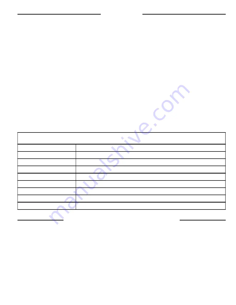
IGN LED DIAGNOSTIC INDICATOR

FLASHING SLOW

NORMAL CALL FOR HEAT

CONTINUOUS ON

NORMAL

CONTINUOUS OFF

CHECK POWER / INTERNAL FAILURE

2 FLASHES

SYSTEM LOCKOUT  ( NO FLAME )

3 FLASHES

PRESSURE SWITCH PROBLEM

4 FLASHES

HIGH LIMIT (TCO) OPEN

5 FLASHES

FLAME SENSED WITH GAS VALVE OFF

6 FLASHES

FLAME ROLLOUT SWITCH (FL) OPEN

7 FLASHES

W1 & W2 SWAPPED

Summary of Contents for YCP-IOM-1C

Page 1: ...h NATIONAL STATE AND LOCAL CODES IMPORTANT This Document is customer property and is to remain with this unit Please return to service information pack upon completion of work Single Package Gas Elect...

Page 2: ...ed application The power supply must be adequate for both the unit and all accessories 3 Check to be sure the refrigerant charge has been retained during shipment Access to 1 4 flare pressure taps may...

Page 3: ...F H YCP042F M YCP048F H YCP060F M TYPICAL ROOFTOP INSTALLATION WITH FULL PERIMETER CURBS YCP024 036F L M Models on BAYCURB030 38A 1 2 ROOF INSULATION ROOF DECK FIELD SUPPLIED RIGID INSULATION SUPPLY A...

Page 4: ...6 1 2 36 29 3 16 18 9 16 11 1 16 6 9 16 6 13 16 17 21 21 7 8 YCP030F L 84 68 93 111 356 YCP030F M 85 70 94 114 363 YCP036F L 88 73 97 114 372 20 1 2 25 1 8 YCP036F M 88 74 97 119 379 YCP036F H 93 76 1...

Page 5: ...30F L YCP030F M YCP036F L YCP036F M YCP036F H 64 36 29 3 16 26 9 16 YCP042F M YCP048F H 65 1 8 45 33 5 8 27 15 16 YCP060F M RECOMMENDED SERVICE CLEARANCE BACK 6 0 LEFT SIDE 30 0 RIGHT SIDE 24 0 FRONT...

Page 6: ...S SERVICE CLEARANCE LINES A B C D SUPPLY AIR RETURN AIR NOTE SUPPLY OPENING 1 REMOVE SCREW NEAREST TO THE OPENINGANDPULLTHEPANELFIRMLY TOWARD THE OUTSIDE OF THE UNIT TO DISENGAGE THE BACK ATTACHMENT R...

Page 7: ...to be inadequate should be reviewed with a local engineer 3 See the unit s nameplate for the absolute minimum clearance between the unit and any combustible surface s IMPORTANT 1 Remove the Flue and...

Page 8: ...with Section 5 3 Air For Combustion and Ventilation of the National Fuel Gas Code ANSIZ223 1 Latest Revision or applicable provisions of the local building code PLACING AND RIGGING 1 Before preparing...

Page 9: ...th a perimeter drip lip that is lower that the unit base bar see Figure 7 inset A 2 Position the unit drip lip down over and in contact with the outside corner of the curb as illustrated in Figure 8 i...

Page 10: ...OP APPLICATION WITH FRAME YCP024 060F 9 4 Place the unit on the frame or roof curb Refer to Figures 9 or 10 5 Secure the unit to the frame or roof curb 6 Insulate any ductwork outside of the structure...

Page 11: ...ine downward away from the unit Avoid long horizontal runs See Figure 12 NOTE Do not use reducing fittings in the drain lines The condensate drain must be Made of 3 4 pipe size Pitched 1 4 per foot to...

Page 12: ...State of California law Proposition 65 WARNING This product contains fiberglass wool insulation Fiberglass dust and ceramic fibers are believed by the State of California to cause cancer through inha...

Page 13: ...PRESSURE SET UP PRECAUTIONS IMPORTANT The furnace and its individual shut off valve must be disconnected from the gas supply piping system during any pressure testing of that system at test pressures...

Page 14: ...3 8 inches water column 5 Using an appropriate backup wrench on the gas valve inlet boss connect the gas piping to the unit Check the completed piping for leaks using a soap and water solution or the...

Page 15: ...instructions to test unit s function 10 Mark an X below the new input column on unit nameplate Attach conversion label to the unit below the nameplate NOTE Do not convert to high fire when the units a...

Page 16: ...xible conduit supports whenever vibration transmission may cause a noise problem within the building structure Be sure all connections are made tight See Figure 18 NOTES For branch circuit wiring main...

Page 17: ...e leaving the unit or turning on the power to the unit ELECTRICAL WIRING YCP F FIELD WIRING DIAGRAM i After all electrical wiring is complete set the thermostat system switch in the OFF position so th...

Page 18: ...rge pressures and compare them to the normal operating pressures provided in the unit s SERVICE FACTS NOTE Do not use the pressures from the unit s SERVICE FACTS to determine the unit refrigerant char...

Page 19: ...ulator located on the front side of the unit s gas valve b Turn the adjusting screw clockwise to increase manifold pressure or counterclockwise to decrease manifold pres sure 3 Check the temperature r...

Page 20: ...d the gas valve GV is de energized instantly The ignition control module IGN then enters the retry mode The retry mode allows the control IGN to purge for 60 seconds Following this time period the val...

Page 21: ...on Pressure Too High Suction Pressure Too Low Liquid Refrigerant floodback TXV System Liquid Refrig floodback Cap Tube System I D Coil Frosting Compressor Runs Inadequate or No Cooling Compressor O D...

Page 22: ...iring to verify that all electrical connections are tight and that the wire insulation is intact Check the operation of the gas ignition system as follows Turn off the gas supply with the unit operati...

Page 23: ...ce labor and diagnosis calls are not included This limited warranty does not cover failure of your combination gas electric air conditioner if it is damaged while in your possession damage caused by u...

Page 24: ...warehouse at Warrantor designated shipping point freight allowed to Buyer s city replacement parts for Warrantor s products covered under this warranty Warrantor shall not be obligated to pay for the...

Reviews: