44
18-CE15D1-1C-EN
Sequence of Operation
E
EA
AC
C a
an
nd
d H
HU
UM
M T
Tiim
miin
ng
g
•
EAC relay closes approximately 5 seconds after the
blower starts.
•
EAC relay opens when the blower motor stops.
•
HUM relay closes on a gas heating call when the
blower motor starts and flame is sensed.
•
HUM relay opens when flame is no longer sensed,
i.e. thermostat is satisfied.
N
No
otte
e:: The EAC and HUM terminals are dry contacts, no
power output.
G
Ga
ass H
He
ea
attiin
ng
g
N
No
otte
e:: There are two main thermal limits on this unit.
Thermal Limit 1 is the primary limit for upflow
applications with right side return ducting.
Thermal Limit 2 is the primary limit for all other
applications.
1. R – W contacts close on the thermostat sending
24VAC to the W low voltage terminal of the IFC.
Technician should read 24VAC from W to C. The
seven segment LED display will show
H
HT
T 1
1
.
2. The IFC performs a self-check routine and then
confirms that the:
a. Main thermal limits (HI LIMIT), burner box
limit (BBOX LIMIT), and reverse air flow
(RAF) switches are closed by sending 24VAC
out of the HLO terminal and monitoring the
HLI input for 24VAC.
b. The IFC then checks the inducer and blower
motor communications.
3. Once step 2a and 2b are confirmed, the variable
speed inducer motor is energized and performs a
30 seconds pre-purge and then shuts down.
4. Once the pre-purge, the igniter warm up period
begins.
a. Eight seconds after the ignitor warm-up
begins, the inducer is energized and ramps
up to meet the Light-Off pressure.
b. Once the Light-Off pressure feedback is
sensed and the igniter warm-up time has
elapsed (~17 seconds), the 1
st
stage gas
valve is energized.
N
No
otte
e:: If the feedback is not correct, the IFC
will time out and flash the proper fault
code.
5. The burner system will ignite, providing current to
the flame sensor. Proof of flame must be
established within 4 seconds or a retry will occur.
N
No
otte
e:: Typical flame current ranges from 0.75 –
3.0µa.
6. Once flame sense has been established, the igniter
is de-energized, the blower on timer begins and the
inducer ramps to the “Pre-Run” speed. During this
transition, the combustion pressure increases until
the Pre-Run pressure is sensed.
7. Once the Pre-Run pressure feedback is sensed, the
IFC will energize the 2nd stage of the gas valve.
8. After the blower on timer has completed, the indoor
blower will run at the selected gas heating speed.
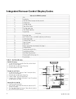
9. The seven segment LED will alternately read:
•
H
HT
T 1
1
= Gas heating, Stage 1
•
A
AR
RF
F
= Airflow
•
0
06
60
0
= 600 calculated cfm (value shown x 10)
(example value)
10. When the temperature raises enough to satisfy the
thermostat setting, contacts R-W will open.
11. The gas valve relay will open, closing the gas valve.
The inducer continues to run for ~5 seconds to
remove any combustion by-products from inside
the furnace.
12. The indoor blower continues to run to remove heat
from the heat exchangers. The Heat Off Delay is
field adjustable. The seven segment LED will return
to
1
1 D
DL
L
(Idle) assuming there is no other demand
from the thermostat, i.e., continuous fan call.
S
Siin
ng
glle
e S
Stta
ag
ge
e C
Co
oo
olliin
ng
g
N
No
otte
e:: Factory supplied Y1-O jumper must remain in
place for proper seven segment LED readout. If
removed, seven segment LED will read
H
HP
P 1
1
1. R-Y1-G contacts on the thermostat close sending
24VAC to the Y1 and G low voltage terminals on the
IFC. Technician should read 24VAC between Y1-B/C
and between G-B/C.
2. 24VAC is sent to the OD unit via thermostat wiring.
3. The indoor blower ramps to the cooling airflow.
The seven segment LED for example will alternately
read:
•
C
CL
L 1
1
= Cooling, Stage 1
•
A
AR
RF
F
= Airflow
•
0
08
80
0
= 800 calculated cfm (value shown x 10)
4. When the temperature is lowered enough to satisfy
the thermostat setting, contacts R-Y-G will open.
5. The OD unit shuts off and the indoor blower shuts
off, unless a blower off delay has been enabled in
the IFC setup menu options. The seven segment
LED will read
1
1 D
DL
L
= Idle, no thermostat demand.

