


TPC6000
‐
A2152
User
Manual
24
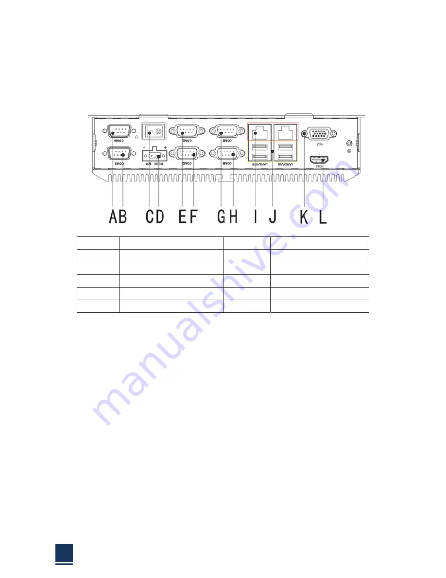
2.7
Bottom
panel
connectors
The
bottom
panel
connectors
extend
the
capabilities
of
the
panel
PC
but
are
not
essential
for
operation
(except
power)
A:
COM6
G:
COM3
B:
COM5
H:
COM4
C:
ATX
I:
LAN
D:
DC
IN
J:
USB
2.0*3/USB
3.0*1
E:
COM1
K:
VGA
F:
COM2
L:
HDMI
Figure
2
‐
12:
Connectors
2.7.1
LAN
connection
The
RJ
‐
45
connectors
enable
connection
to
an
extend
network.
To
connect
a
LAN
cable
with
a
RJ
‐
45
connector,
please
follow
the
instructions
below.
Step
1:
Locate
the
RJ
‐
45
connector
on
the
bottom
panel
of
the
TPC6000
‐
A2152
‐
T.
Step
2:
Align
the
connectors.
Align
the
RJ
‐
45
connector
on
the
LAN
cable
with
one
of
the
RJ
‐
45
connector
on
the
bottom
panel
of
the
TPC6000
‐
A2152
‐
T.
Please
See
Figure
2
‐
13
Summary of Contents for TPC6000-A2152
Page 1: ...TPC6000 A2152 User Manual 1 User Manual Ver1 0 TPC6000 A2152 Industrial Panel PC ...
Page 8: ...TPC6000 A2152 User Manual 8 Chapter 1 OVERVIEW ...
Page 14: ...TPC6000 A2152 User Manual 14 1 6 Dimensions Figure 1 5 TPC6000 A2152 T dimensions ...
Page 15: ...TPC6000 A2152 User Manual 15 Chapter 2 INSTALLATIONS ...
Page 34: ...TPC6000 A2152 User Manual 34 Press NEXT to continue ...
Page 41: ...TPC6000 A2152 User Manual 41 Press YES to continue ...
Page 44: ...TPC6000 A2152 User Manual 44 Press NEXT to continue ...
Page 46: ...TPC6000 A2152 User Manual 46 ...
Page 49: ...TPC6000 A2152 User Manual 49 Press NEXT to continue Press INSTALL to continue ...
Page 55: ...TPC6000 A2152 User Manual 55 Chapter 3 BIOS Setup ...
Page 60: ...TPC6000 A2152 User Manual 60 Figure 3 3 1 PCI Subsystem Configuration Setting ...
Page 61: ...TPC6000 A2152 User Manual 61 3 3 2 ACPI Setting Figure 3 3 2 ACPI Configuration Setting ...
Page 64: ...TPC6000 A2152 User Manual 64 3 3 5 USB Configuration Figure 3 3 5 USB Configuration ...
Page 66: ...TPC6000 A2152 User Manual 66 3 3 7 PC Health Status Figure 3 3 7 PC Health status ...
Page 67: ...TPC6000 A2152 User Manual 67 3 3 8 PPM Configuration Figure 3 3 8 PPM Configuration ...
Page 68: ...TPC6000 A2152 User Manual 68 3 4 Chipset Settings host bridge Figure 3 4 Chipset Settings ...
Page 69: ...TPC6000 A2152 User Manual 69 3 4 1 Intel graphic configuration ...
Page 71: ...TPC6000 A2152 User Manual 71 3 5 Chipset settings south bridge Figure 3 5 Chipset Settings ...
Page 73: ...TPC6000 A2152 User Manual 73 3 5 2 Power on configuration Figure 3 5 3 Power on Settings ...
Page 75: ...TPC6000 A2152 User Manual 75 Figure 3 5 3 Boot configuration ...
Page 76: ...TPC6000 A2152 User Manual 76 3 6 Security settings Figure 3 6 Security settings ...
Page 79: ...TPC6000 A2152 User Manual 79 Chapter 4 System Maintenance ...
Page 81: ...TPC6000 A2152 User Manual 81 A Safety Precautions ...
Page 85: ...TPC6000 A2152 User Manual 85 B ALC662 Digital Microphone Configuration ...
Page 89: ...TPC6000 A2152 User Manual 89 C Watchdog Timer ...
Page 92: ...TPC6000 A2152 User Manual 92 D Hazardous Materials Disclosure ...
Page 95: ...TPC6000 A2152 User Manual 95 Chapter 5 Appendix A ...


