


TPC6000
‐
A2152
User
Manual
21
To
install
the
TPC6000
‐
A2152
‐
T
on
the
arm,
follow
the
direction
below:
Notice:
Make
sure
the
arm
supports
standard
VESA
mounting.
The
TPC6000
‐
A2152
‐
T
uses
a
VESA
mounting
to
attach
to
the
arm.
Step
1:
The
arm
purchased
separately,
follow
the
instructions
in
the
arm’s
user
manual
to
securely
attach
the
arm
to
the
wall.
Step
2:
Once
the
mounting
arm
has
been
firmly
attached
to
the
surface,
lift
the
flat
panel
PC
onto
the
interface
pad
of
the
mounting.
Step
3:
Align
the
retention
screw
holes
on
the
mounting
arm
interface
with
those
in
the
flat
panel
PC.
Step
4:
Secure
the
flat
panel
PC
to
the
interface
pad
by
inserting
four
retention
screws
through
the
bottom
of
the
mounting
arm
interface
pad
and
into
the
flat
panel
PC.
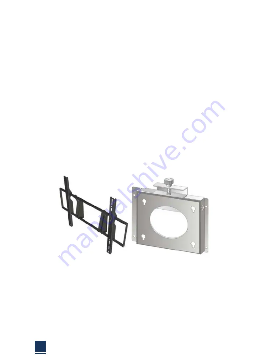
2.6.3
Wall
mounting
To
mount
the
flat
panel
PC
onto
the
wall,
please
follow
the
steps
below:
Figure
2
‐
9:
Wall
mount
Step
1:
Select
the
location
on
the
wall
for
the
wall
‐
mounting
bracket.
Step
2:
Carefully
mark
the
locations
of
the
four
bracket
screw
holes
on
the
wall.
Step
3:
Drill
four
pilot
holes
at
the
marked
locations
on
the
wall,
for
the
bracket
retention
screws.
Step
4:
Align
the
wall
‐
mounting
bracket
screw
holes
with
the
pilot
holes.
Step
5:
Secure
the
mounting
‐
bracket
to
the
wall
by
inserting
the
retention
screws
into
the
four
pilot
holes
and
tightening
them
Summary of Contents for TPC6000-A2152
Page 1: ...TPC6000 A2152 User Manual 1 User Manual Ver1 0 TPC6000 A2152 Industrial Panel PC ...
Page 8: ...TPC6000 A2152 User Manual 8 Chapter 1 OVERVIEW ...
Page 14: ...TPC6000 A2152 User Manual 14 1 6 Dimensions Figure 1 5 TPC6000 A2152 T dimensions ...
Page 15: ...TPC6000 A2152 User Manual 15 Chapter 2 INSTALLATIONS ...
Page 34: ...TPC6000 A2152 User Manual 34 Press NEXT to continue ...
Page 41: ...TPC6000 A2152 User Manual 41 Press YES to continue ...
Page 44: ...TPC6000 A2152 User Manual 44 Press NEXT to continue ...
Page 46: ...TPC6000 A2152 User Manual 46 ...
Page 49: ...TPC6000 A2152 User Manual 49 Press NEXT to continue Press INSTALL to continue ...
Page 55: ...TPC6000 A2152 User Manual 55 Chapter 3 BIOS Setup ...
Page 60: ...TPC6000 A2152 User Manual 60 Figure 3 3 1 PCI Subsystem Configuration Setting ...
Page 61: ...TPC6000 A2152 User Manual 61 3 3 2 ACPI Setting Figure 3 3 2 ACPI Configuration Setting ...
Page 64: ...TPC6000 A2152 User Manual 64 3 3 5 USB Configuration Figure 3 3 5 USB Configuration ...
Page 66: ...TPC6000 A2152 User Manual 66 3 3 7 PC Health Status Figure 3 3 7 PC Health status ...
Page 67: ...TPC6000 A2152 User Manual 67 3 3 8 PPM Configuration Figure 3 3 8 PPM Configuration ...
Page 68: ...TPC6000 A2152 User Manual 68 3 4 Chipset Settings host bridge Figure 3 4 Chipset Settings ...
Page 69: ...TPC6000 A2152 User Manual 69 3 4 1 Intel graphic configuration ...
Page 71: ...TPC6000 A2152 User Manual 71 3 5 Chipset settings south bridge Figure 3 5 Chipset Settings ...
Page 73: ...TPC6000 A2152 User Manual 73 3 5 2 Power on configuration Figure 3 5 3 Power on Settings ...
Page 75: ...TPC6000 A2152 User Manual 75 Figure 3 5 3 Boot configuration ...
Page 76: ...TPC6000 A2152 User Manual 76 3 6 Security settings Figure 3 6 Security settings ...
Page 79: ...TPC6000 A2152 User Manual 79 Chapter 4 System Maintenance ...
Page 81: ...TPC6000 A2152 User Manual 81 A Safety Precautions ...
Page 85: ...TPC6000 A2152 User Manual 85 B ALC662 Digital Microphone Configuration ...
Page 89: ...TPC6000 A2152 User Manual 89 C Watchdog Timer ...
Page 92: ...TPC6000 A2152 User Manual 92 D Hazardous Materials Disclosure ...
Page 95: ...TPC6000 A2152 User Manual 95 Chapter 5 Appendix A ...


