background image

American-Lincoln Technology 

FORM NO. 56041667 - 7

7765 / 7760

CONSIGNES DE PRUDENCE ET DE SECURITE
SYMBOLES

American-Lincoln

 - Alto utilise les symboles reproduits ci-dessous pour attirer l’attention de l’opérateur sur des situations potentiellement 

dangereuses. Il est donc conseillé de lire attentivement ces indications et de prendre les mesures adéquates en vue de protéger le 
personnel et le matériel.

 DANGER 

!

Ce symbole est utilisé pour mettre l’opérateur en garde contre les risques immédiats pouvant provoquer des dommages corporels 
graves, voire entraîner la mort.

 ATTENTION 

!

Ce symbole est utilisé pour attirer l’attention sur une situation susceptible d’entraîner des dommages corporels graves.

 PRUDENCE 

!

Ce symbole est utilisé pour attirer l’attention de l’opérateur sur une situation qui pourrait entraîner des dommages corporels minimes ou 
des dommages à la machine ou à d’autres équipements.

  Lire toutes les instructions avant d’utiliser l’appareil. 

CONSIGNES GENERALES DE SECURITE

Les consignes spécifi ques de prudence et de sécurité mentionnées ici ont pour but de vous informer de la survenance de tout risque 
de dommages matériels ou corporels.

 DANGER 

!


Les gaz d’échappement (monoxyde de carbone) évacués par la machine peuvent entraîner de graves dommages corporels, voire 
la mort. Veillez donc toujours à bénéfi cier d’une ventilation suffi sante lorsque vous utilisez la machine.

 ATTENTION 

!


Cette machine ne pourra être utilisée que par du personnel parfaitement entraîné et dûment autorisé.


Evitez les arrêts subits lorsque la machine est chargée et se trouve sur des rampes ou des plans inclinés. Evitez les virages serrés. Adoptez 
une vitesse réduite lorsque la machine est en descente. Ne nettoyez que lorsque la machine monte la pente.


Lorsque vous utilisez le système hydraulique ou travaillez à proximité de celui-ci, veillez à porter une tenue appropriée et des lunettes de 
protection afi n d’éviter tout risque de blessures ou toute projection d’huile.


Positionnez la clé de contact sur off (O) et déconnectez les batteries avant de procéder à l’entretien des composants électriques.


Ne travaillez jamais sous une machine sans y avoir placé, au préalable, des blocs de sécurité ou des étais destinés à soutenir la 
machine


Ne déversez pas d’agents nettoyants infl ammables, ne faites pas fonctionner la machine à proximité de ces agents ou d’autres liquides 
infl ammables.


Ne nettoyez pas cette machine avec un nettoyeur à pression.

 PRUDENCE 

!


Cette machine n’est pas conçue pour une utilisation sur les chemins ou voies publiques.


Cette machine n’est pas conçue pour le ramassage des poussières dangereuses.


Faites extrêmement attention lorsque vous utilisez des disques de scarifi cateur et des meules. American-Lincoln

 - Alto ne pourra, en 

aucun cas, être tenu pour responsable des dommages occasionnés à vos sols par ce type d’équipement.


Lors de l’utilisation de cette machine, assurez-vous que des tiers, et notamment des enfants, ne courent pas le moindre risque.


Avant de procéder à toute opération d’entretien, veuillez lire attentivement toutes les instructions qui s’y rapportent.


Ne laissez pas la machine sans surveillance sans avoir, au préalable, coupé le contact, enlevé la clé de contact (O) et tiré le frein à 
main.


Positionnez la clé de contact sur off (O) avant de remplacer les brosses ou d’ouvrir tout panneau d’accès.


Prenez toutes les mesures nécessaires pour éviter que les cheveux, les bijoux ou les vêtements amples ne soient entraînés dans les 
parties mobiles de la machine.


Faites attention lorsque vous déplacez cette machine dans un endroit où la température peut descendre sous 0°. Car l’eau contenue dans 
la solution, dans les réservoirs de récupération ou dans les conduites risquerait de geler.


Avant utilisation, toutes les portes et capots doivent être correctement fermés.

CONSERVEZ SOIGNEUSEMENT CES INSTRUCTIONS

Summary of Contents for 7760

Page 1: ...t in injury to you or to other personnel damage to the machine or to other property could occur as well You must have training in the operation of this machine before using it All directions given in this book are as seen from the operator s position at the rear of the machine 7765 7760 SCRUBBER SWEEPER Form Number 56041667 Revised 1 07 English 7765 505 255 505 258 505 256 505 259 505 257 505 260 ...

Page 2: ...M SWITCH 10 SIDE BROOM SWITCH 10 DUST CONTROL SWITCH 10 FILTER SHAKER SWITCH 10 WATER TEMPERATURE GAUGE 11 HOUR METER 11 FUEL GAUGE 11 OIL PRESSURE GAUGE 11 VOLT METER 11 SCRUB BRUSHES SWITCH 11 BRUSH ROTATION SWITCH 12 BRUSH PRESSURE SWITCH 12 SQUEEGEE BLADE SWITCH 12 HIGH RECOVERY WARNING LIGHT 12 LOW SOLUTION WARNING LIGHT 12 HOPPER LIFT 13 HOPPER SAFETY LOCK ARM 13 HOPPER DUMP DOOR 13 MANUAL D...

Page 3: ...E CLEANING OPERATION 21 HELPFUL HINTS FOR CLEANING OPERATION 22 POST OPERATION CLEAN UP INSTRUCTIONS 23 TO STOP THE CLEANING OPERATION 23 POST OPERATION CHECKLIST 23 TO DRAIN THE SOLUTION TANK 23 TO CLEAN THE SOLUTION TANK 23 TO DRAIN THE RECOVERY TANK 23 TO CLEAN THE RECOVERY TANK 24 TO EMPTY THE DEBRIS HOPPER 25 TOWING INSTRUCTIONS 25 SERVICE CHART 26 GENERAL MACHINE MAINTENANCE 28 LUBRICATION 2...

Page 4: ...ticker here NAMEPLATE The Model Number and Serial Number of your machine are shown on the Nameplate located on the wall of the operator s compartment This information is needed when ordering repair parts for the machine Use the space below to note the Model Number and Serial Number of your machine for future reference MODEL _____________________________________ SERIAL NUMBER ______________________...

Page 5: ...Check engine crankcase oil level Although properly lubricated at factory check before starting engine No special brand oil is used Recommended number of operating hours before the initial oil change is the same as normal See Maintenance 4 Check radiator coolant level Permanent type antifreeze is added at the factory to provide protection to approximately 35 F 37 C To retain this protection level a...

Page 6: ...orking with or near hydraulic system Turn the key switch off O and disconnect the batteries before servicing electrical components Never work under a machine without safety blocks or stands to support the machine Do not dispense flammable cleaning agents operate the machine on or near these agents or operate in areas where flammable liquids exist Do not clean this machine with a pressure washer CA...

Page 7: ...é de celui ci veillez à porter une tenue appropriée et des lunettes de protection afin d éviter tout risque de blessures ou toute projection d huile Positionnez la clé de contact sur off O et déconnectez les batteries avant de procéder à l entretien des composants électriques Ne travaillez jamais sous une machine sans y avoir placé au préalable des blocs de sécurité ou des étais destinés à souteni...

Page 8: ...ROLS AND GAUGES IGNITION SWITCH The keyed ignition switch is located to the right of the steering column on the front face of the instrument console It has four positions 1 The key turned to the center OFF position will shut off the engine The following items can be activated in the OFF position A Horn B Light Options 2 The key turned to the right IGN ON position will allow all the following items...

Page 9: ...tarter motor press the GLOW PLUG button for 20 to 30 seconds 2 With the GLOW PLUG button still depressed engage the starter motor until the engine starts 3 Continue to press the GLOW PLUG button for a few seconds after the engine has started until even running has been obtained 4 If the engine does not start disengage the starter motor but keep the GLOW PLUG button depressed for an additional 10 t...

Page 10: ...Variable Dump Machines Only The Filter Shaker Switch is located on the console to the right of the steering wheel in the SWEEPING section NOTE Variable Dump Machines Only THE MAIN BROOM SWITCH MUST ALWAYS BE PLACED IN THE OFF POSITION BEFORE SHAKING THE FILTER FAILURE TO DO SO WILL RESULT IN DUST REMAINING ON THE SURFACE OF THE FILTER ENVELOPES INSTEAD OF DROPPING INTO THE HOPPER The button can be...

Page 11: ...als FUEL GAUGE The Fuel Gauge is located on the console panel above the steering wheel in the gauge cluster This gauge indicates the level of fuel contained in the fuel tank OIL PRESSURE GAUGE The Oil Pressure Gauge is located on the console panel above the steering wheel in the gauge cluster The gauge is mechanical and activated by a sender in the engine It displays the engine oil pressure in PSI...

Page 12: ...less the Scrub Brush Lift Switch is in the LOWER position The switch will light when the switch can be activated SQUEEGEE BLADE SWITCH The Squeegee Blade Switch is located on the console to the left of the steering wheel in the SCRUBBING section This switch in the position marked LOWER will lower the squeegee and activate the squeegee vacuum This switch in the RAISE position will stop the squeegee...

Page 13: ...n clear of the debris pull the manual dump lever to the position marked closed SOLUTION CONTROL To apply solution to the scrubbing brushes push the solution control lever forward until the desired setting is reached The solution rate is continuously variable from off to approximately 1 3 4 GPM at low and 3 1 2 GPM at high To stop application of solution pull back on the lever until it stops at the...

Page 14: ...ushes and or dust control operating and No Load brooms brushes dust control off RPMs are the same for gas and LP equipment The will be a slight drop between Load and No Load RPMs with diesels Always return the throttle switch lever to the idle position before turning off the key to stop the engine CHECK ENGINE LIGHT MIL Gas LP Only The check engine light MIL is located on the left side console If ...

Page 15: ...e pedal The machine will move in reverse 4 Increase the foot pressure on the lower portion of the pedal to increase the reverse speed 5 To stop the machine put light foot pressure on the opposite end of the accelerator and directional control pedal If the machine is moving forward put light foot pressure on the lower portion of the pedal If the machine is moving in reverse put light foot pressure ...

Page 16: ...TION HIGH WARNING LIGHT The solution high warning light will come on if the solution tank is too full of water from the recycling system DETERGENT LOW WARNING LIGHT The detergent light will illuminate when the detergent tank is low warning the operator to add detergent DETERGENT FLOW KNOB This rotary knob controls the detergent flow into the scrubbing solution The operator may choose from any dete...

Page 17: ...TING INSTRUCTIONS THE SCRUBBING SYSTEM HOW IT WORKS There are two scrubbing systems available for the 7765 7760 machine the non recycling or standard scrubbing system and the recycling or ESP scrubbing system THE NON RECYCLING OR STANDARD SCRUBBING SYSTEM HOW IT WORKS During the scrubbing process shown in Figure 14 detergent solution water from the solution tank is fed to the solution line There i...

Page 18: ... it combines with detergent from the metering pump This mixture is then fed to the floor where three disc scrubbing brushes work to dislodge soil After scrubbing the dirty solution is vacuumed from the floor and discharged into the containment chamber in the forward portion of the recovery tank where a system of baffles helps to clarify the solution on its way to the pumping chamber in the rear of...

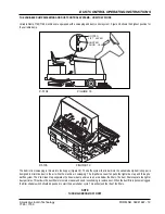
Page 19: ...igure 19 The baffle system that is built into the variable dump debris hopper is designed to minimize dust in the air while the machine is sweeping The impeller vacuum fan pulls the lighter dust up and through a baffle system The Pre Clean Flap separates the heavier dust particles to an area below the filters The dust filters capture the lighter dust particles This allows the dust filters to remai...

Page 20: ... 100 WARNING DO NOT put gasoline combustible or other flammable material in the solution recovery or detergent tanks NOTE Before starting the engine perform the pre start checklist PRE START CHECKLIST 1 Clean engine air filter element if needed 2 Check engine oil level 3 Check radiator coolant level 4 Check hydraulic fluid level 5 Check fuel level 6 Check all systems for leaks 7 Check brakes and c...

Page 21: ...utral when foot pressure is released FOR NORMAL OPERATION DEPRESS DIRECTIONAL CONTROL PEDAL WITH HEEL INTO NEUTRAL 7 Push engine throttle down Turn key to Off 8 Set parking brake TO BEGIN THE CLEANING OPERATION 1 Choose the mode of operation recycling ESP or non recycling STANDARD as dictated by the machine fill or machine type 2 Bring engine to full RPM 3 Lower the main broom 4 Lower the side bro...

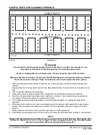
Page 22: ... debris before sweeping 3 Allow a few inches overlap of sweep and scrub paths This will eliminate leaving dirty patches 4 Don t turn steering wheel too sharply when machine is in motion The machine is very responsive to movement of the steering wheel so avoid sudden turns 5 Try to follow as straight a path as possible Avoid bumping into posts or scraping the sides of the machine 6 When placing the...

Page 23: ... Drain and clean recovery tank 7 Clean recovery tank screens and floats 8 Check manifold and vacuum hoses for debris or obstructions backflush if necessary 9 Check scrub brushes for wear or damage 10 Check rear and side squeegees for wear damage and adjustment 11 Fill fuel tank 12 Check all systems for leaks TO DRAIN SOLUTION TANK RECYCLING OPERATION ESP System Draining the solution tank is accomp...

Page 24: ...position figure 20 flush all sand sludge debris etc out of the tank with a water hose then replace the tank and flush the manifold ball float screen and level switch to remove any deposits The tank lid should be removed and cleaned approximately every 50 running hours WARNING Do not attempt to flush large amounts of tank debris through the drain hose This will cause clogging and hamper future drai...

Page 25: ...opper with the hopper lift lever to the normal operation position NOTE Variable Dump Only The sweep functions main broom side broom dust fan and filter shakers only work when the hopper is down and the dump door is open TOWING INSTRUCTIONS See Figure 22 1 Locate tow control shaft extension as shown in Figure 22 See arrow 2 To open hydraulic circuit to wheel drive motor turn shaft 90 so that the fl...

Page 26: ... Perform recommended engine maintenance see engine manual if applicable 100 HOUR MAINTENANCE CHECKLIST 25 Change crankcase oil 26 Change engine oil filter 27 Lubricate drive wheel l swivel wheel bearings and steering rack guide engine side above rear wheel MAKE SURE TO GREASE ZERK LOCATED ABOVE PINION RACK See Rear Wheel Assy Chapter 2 28 Lubricate front wheel bearings 29 Lubricate all moving join...

Page 27: ...American Lincoln Technology FORM NO 56041667 27 7765 7760 SERVICE CHART 11 34 17 16 20 2 25 39 36 37 4 13 35 38 26 21 9 31 31 8 15 33 14 3 29 1 7 24 41 42 43 12 40 31 27 32 18 29 5 31 6 23 28 30 19 ...

Page 28: ...s LP DANHOUSER Bushings with NAPA 765 1363 or equivalent anti seize lubricant The bushings are located on the steering scrub deck lift squeegee lift main broom lift both threaded ends of the throttle cable and the variable dump door cylinders 250 Hour Lubrication 5 Lubricate squeegee casters 6 Lubricate governor linkage Diesel Use good grade multipurpose grease Avoid using too much grease 6 3 4 2 ...

Page 29: ...SWEEPING BROOM 1 Open the left broom chamber door 2 Put the main broom control in the SWEEP position 3 Remove the retaining bolt 4 Remove the idler arm assembly 5 Remove the main broom and discard 6 Put a new main broom in the broom chamber 7 Rotate the new broom to the right on the drive hub until it engages the drive hub broom tabs 8 Put the idler arm assembly in place 9 Put the retaining bolt i...

Page 30: ...ine compartment 2 Set the broom lever to the Sweep position and adjust the lock nut to obtain a 2 inch 5 cm broom pattern The lock nut will move the adjusting rod that adjusts the sweeping pattern of the broom for wear GENERAL MACHINE MAINTENANCE SIDE BROOM LEVEL ADJUSTMENT As the side broom wears loosen the two wear adjusting bolts and slide the broom motor assembly into a position so that the br...

Page 31: ...nspected regularly and maintained in good condition The side flaps are adjustable and should be maintained at approximately 1 16 16 mm above the floor The front and rear flaps have no provision for adjustment All flaps should be replaced when worn or damaged to such an extent that they couldn t perform their function 1 16 SET FLAP EVEN WITH FLOOR P 4793 FIGURE 30 ...

Page 32: ...enance except for daily cleaning of the tank level switch If the system fails to operate consult the Electrical Troubleshooting Guide SOLUTION CONTROL Non Recycling or Standard The solution control lever controls the amount of solution applied to the scrubbing brushes Except for a few drops of oil applied to the lever pivot every 100 hours the system should require no major maintenance The solutio...

Page 33: ...egee support 2 Remove the squeegee tool and turn upside down to service the blades or caster wheels The squeegee blades are designed to flip over and use another unworn edge item 5 6 To service the blades 1 Loosen the clamp bolts which clamp items 8 9 together 2 Loosen far enough to slip the end clamp brackets off the squeegee tool This will allow flipping the blades or installing new blades 3 Ins...

Page 34: ... shut off Poor water pick up at squeegee 1 Side or rear squeegee are worn or damaged 2 Clogging in water pick up 3 Air leaks in suction hose and connection 4 Air leaks at recovery tank cover and or manifold gaskets 5 Poor vacuum 6 Drain hose or drain plug leakage or not closed properly Water spill from squeegee 1 Side squeegee blades poor contact with floor 2 Squeegee blades worn or damages 3 Too ...

Page 35: ... pressure type of brush solution flow cleaning chemical used For extreme conditions double scrubbing may be necessary 3 Use A L recommended materials 4 Clean out distribution tube metering holes to brushes Check feed hose clean if necessary Check valve cable control system 1 Check pedal linkage 2 Check wheels and brakes 3 Check repair pump check tow valve See CESSNA information 4 Check repair See ...

Page 36: ...ons at the Hand Controls ISO 5349 1 m s2 0 89 m s2 0 89 m s2 Vibrations at the Seat EN 1032 m s2 0 31 m s2 0 31 m s2 Gradeability Transport 14 1 8 14 1 8 Cleaning 10 5 6 10 5 6 Model 7760 Petrol VD 7760 Petrol MD 7760 Diesel VD 7760 Diesel MD Model No 505 255CE 505 258CE 505 257CE 505 260CE Sound Pressure Level ISO 11201 dB A 89 4 89 4 Sound Power Level ISO 3744 dB A Lwa 109 0 Lwa 109 0 Total Weig...

Page 37: ......

Page 38: ......

Page 39: ......

Page 40: ...14600 21st Avenue North Plymouth MN 55447 3408 www americanlincoln com Phone 800 331 7692 Fax 877 877 2586 2007 American Lincoln ...

Reviews: