background image

INDOOR DOME INSTALLATION

SPEEDDOME ULTRA

2-21

Attaching the Skirt to the Indoor
SpeedDome Housing (No Bubble
Used)

The following procedure explains how to attach a
skirt to an indoor SpeedDome housing.

Install Kit Required

RHSDA Adapter Bracket*

Skirt assembly w/o bubble

1

0400-0866-01

* Only part used in this procedure is listed.
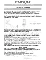
Procedure

Referring to Figure 2-23:

1. Insert the skirt’s T-lanyard into the slot in

the adapter bracket until both ends of the
“T” catch securely.

2. Push pins of the skirt into their respective

receptacles and snap the skirt into place.

Figure 2-23. Attaching the skirt to the indoor

SpeedDome housing

Attaching the Bubble to the Indoor
SpeedDome Housing

The following procedure explains how to attach a
bubble to an indoor SpeedDome housing.

Install Kits Required

RHSDA Adapter Bracket*

a. Skirt, inside bubble

1

0500-7411-01

b. Tape, foam, Vinyl, .062”x.5”

2.5ft

3200-0214-01

* Only parts used in this procedure are listed.

Pick Kit A, B, C, or D:
A) 0351-0386-01 Clear Bubble
B) 0351-0386-02 Silver Bubble
C) 0351-0386-03 Smoked Bubble
D) 0351-0386-04 Gold Bubble
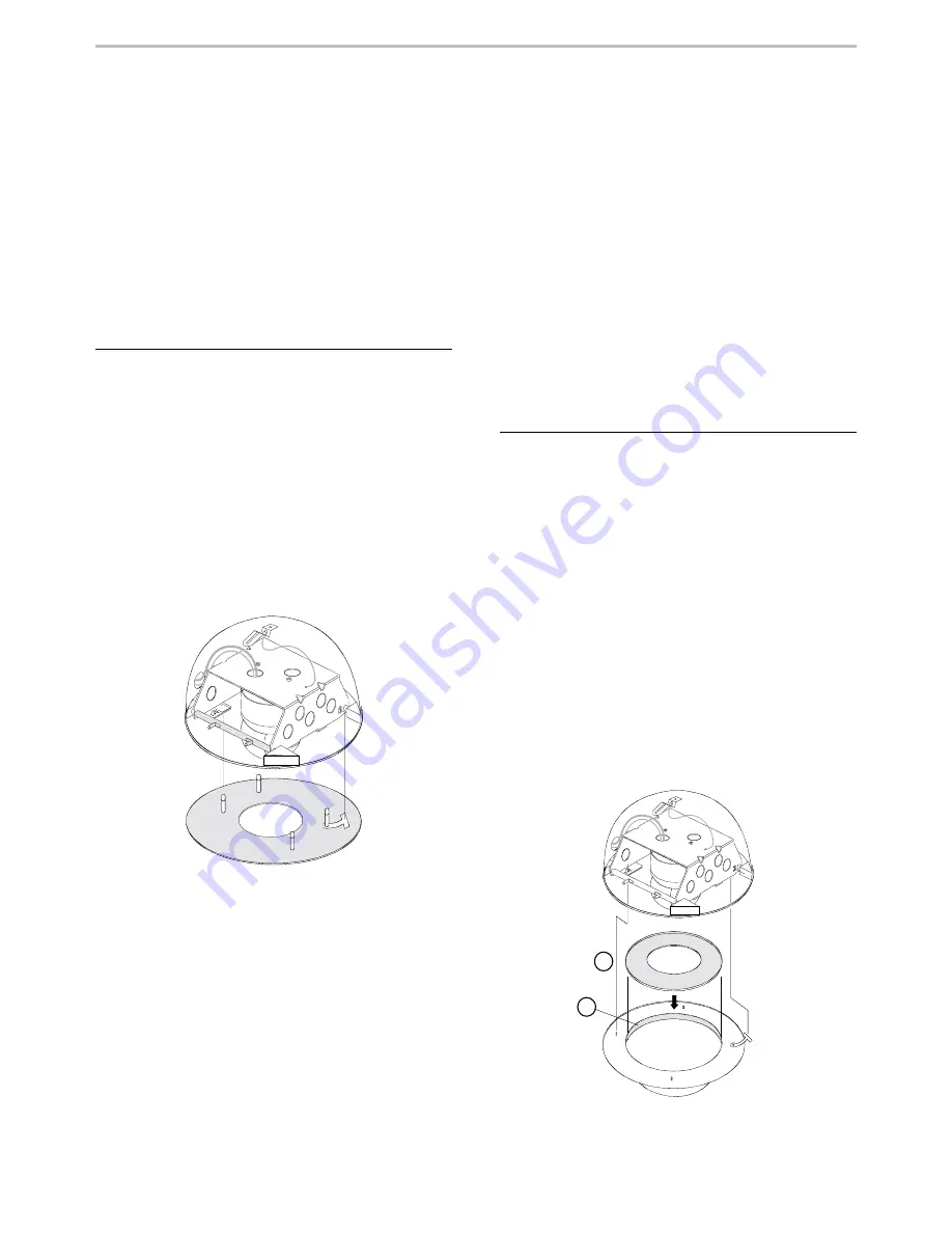
Procedure

Referring to Figure 2-24:

1. Insert the skirt [a] into the bubble assembly.

A layer of foam tape [b] holds the skirt in place.
If the skirt drops below the tape, use the foam
tape supplied to apply an additional layer.

2. Insert the skirt’s T-lanyard into the slot in

the adapter bracket until both ends of the
“T” catch securely.

3. Push pins of the bubble into their respective

receptacles and snap the bubble into place.

Figure 2-24. Attaching the bubble to the indoor

SpeedDome housing

a

b

Summary of Contents for SpeedDome Ultra

Page 1: ...SpeedDome Ultra Camera Dome Installation and Service Manual 8000 1362 01 Rev B ...

Page 2: ...SpeedDome Ultra Camera Dome Installation and Service Manual 8000 1362 01 Rev B MDR 4 97 ...

Page 3: ...Corporation makes no representation or warranty with respect to the contents hereof and specifically disclaims any implied warranties of merchantability or fitness for any particular purpose Further Sensormatic Electronics Corporation reserves the right to revise this publication and make changes from time to time in the content hereof without obligation of Sensormatic Electronics Corporation to n...

Page 4: ...ile ceiling mounting 2 3 Hard ceiling surface mounting 2 3 Tile ceiling surface mounting 2 4 Optional mounting structures 2 5 Top hat housing 2 5 Fixed mounting bracket for hard ceilings or 2x2 ceiling tiles 2 6 Adjustable mounting bracket for 2x4 ceiling tiles 2 8 Wall mounting bracket 2 10 Wall mounting using a corner bracket 2 11 Wall mounting using an arm extension 2 12 Wall mounting using a c...

Page 5: ...and equipment required 4 2 ROUTINE TROUBLESHOOTING 4 2 Dome functions but does not pan 4 3 Dome functions but does not tilt 4 3 Dome does not home or respond to commands dead dome 4 3 DETAILED TROUBLESHOOTING 4 5 DOME DISASSEMBLY TECHNIQUES 4 5 How to remove the CPU board 4 6 How to remove the power supply board 4 6 How to remove the pan motor 4 7 How to remove the slot covers 4 7 How to remove th...

Page 6: ...3 0 0 0 0 OUTDOOR OUTDOOR OUTDOOR OUTDOOR INSTALLATION INSTALLATION INSTALLATION INSTALLATION provides procedures required to mount the dome outdoors 4 4 4 4 0 0 0 0 SERVICE SERVICE SERVICE SERVICE provides troubleshooting and maintenance information Related Documents Installation and service of this camera dome does not require detailed knowlege of how it it works or its circuits However if this ...

Page 7: ...vi ...

Page 8: ... Ultra Camera Dome 1INTRODUCTION n Product overview 1 2 Describes how the dome works its mounting methods major components and features n Specifications 1 9 Lists electrical environmental regulatory and mechanical specifications for the dome ...

Page 9: ...camouflaged lens tilt motor and assoc iated electronics Camouflaged slot cover optional This slot cover has a 0 5f darker lens that enhances eyeball camou flage It can be used in place of the one on the eye ball Camera Options The dome as shipped contains one of four different CCD cameras Color NTSC 60Hz Color PAL 50Hz Monochrome EIA 60Hz Monochrome CCIR 50Hz These cameras have 12X optical zoom wi...

Page 10: ...BW CCIR Screw 1 4 20x3 8 2802 7407 65 Bearing Assy Lens Carriage 2510 0038 01 Yoke Bracket 2 0500 7254 01 Standard Slot Cover with Lens 0500 6709 01 Supplied with Final Assy not Eyeball Assy 0351 1163 01 Install Kit Optional Slot Cover with 0 5f Darker Lens 0500 6709 03 Cable Assy Tilt 0650 1680 01 Slot Cover 0500 6709 02 Supplied with Final Assy not Eyeball Assy Yoke 0500 6709 01 Camera Lens Boar...

Page 11: ... be used with the following bubbles RU105UD Clear bubble RU106UD Silver bubble RU107UD Smoked bubble RU108UD Gold bubble RHIUFB Fixed bracket Allows top hat housing to be recessed into 2x2 drop ceiling or in hard ceilings such as sheet rock plaster and wood requires top hat RHIUH RHIUAB Adjustable bracket Allows the top hat housing to be recessed into 2x4 drop ceiling tiles requires top hat RHIUH ...

Page 12: ...INTRODUCTION SPEEDDOME ULTRA 1 5 Figure 1 5 Indoor mounting structures optional RHIUH RHIUFB RHIUAB RHIUWM RHIULWM RHIUCM RHIUPND RHIU3x3 RHIU4x4 RHSDA ...

Page 13: ...tops DSP Motor Control All lens motors are assembled on a balanced mechanism that supports high speed pan and tilt movements Digital signal processing DSP and dynamic motor braking assure precise and fluid camera movement and accuracy High resolution cameras The dome uses mono chrome and color cameras These cameras have 12X optical zoom with continuous auto focus and backlight compensation An elec...

Page 14: ...n lock Apple peel and flip function keys Loadable program code Console V phase adjustment Flip function Address range from 1 to 8 VM16 System Proportional pan and tilt speed control scaled to zoom position Four programmable targets Three patterns per dome with Apple Peel as default pattern Repeat pattern and flip function keys Alarm inputs and outputs Loadable program code Console V phase adjustme...

Page 15: ...low communications LEDs same as on the J Box indicate that power and data are reaching the dome RS422 communications test pushbutton and LEDs A pushbutton and green and red LEDs on the underside of an installed base allow the installer to check RS422 terminations to the dome The LEDs indicate that RS422 wiring is correct reversed open or grounded Safety The camera dome meets all international regu...

Page 16: ... POS EM 16 with AD2083 02A Unlimited with VM96 Programmable Patterns 3 Alarm Inputs 4 dry contacts 3 5 mA sink Alarm Outputs 4 open collector drivers 12Vdc 40mA Electrical Primary Source 18 to 30Vac 50 60 Hz Design Tolerance 16 to 36Vac 50 60 Hz Current 0 85A max Power On In Rush Current 1 5 A Program Storage 256 Kbytes of Flash memory Data Storage 96 Kbytes of SRAM Surge Protection Video Output 1...

Page 17: ...mination 2 25 lux AGC on White Balance Through the Lens TTL Auto Tracing White balance ATW NTSC Pickup Device 768 H x 494 V pixels Scanning 525 lines 60 fields 30 frames Horizontal 15 734kHz Vertical 59 9 Hz internal sync PAL Pickup Device 752 H x 582 V pixels Scanning 625 lines 50 fields 25 frames Horizontal 15 625kHz Vertical 50Hz Lens Design Aspherical Focal Length 4 to 48 mm Aperture f1 6 View...

Page 18: ...2 INSTALLATION In this chapter n Before You Begin 2 2 Things you need to do before you install the camera dome n Installation Procedure 2 3 Shows you how to mount the dome indoors to either a hard ceiling tile ceiling wall electrical box I beam or existing SpeedDome housing ...

Page 19: ...and 11mm sockets 18 14 AWG and 22 20 AWG wire strippers Install Removal tool to attach and detach domes and bubbles without a ladder Hand vacuum and broom Parts Check Other than these instructions in the shipping box for the dome are the following parts Base assembly 0100 1340 01 Housing and eyeball assembly 0100 1036 01 Installation kit 0351 1109 01 Optional slot cover kit 0351 1163 01 I O Board ...

Page 20: ...t rock or wood beams or to the T bar inter sections of a tile ceiling Hard Ceiling Surface Mounting This procedure explains how to mount the dome s base directly to sheet rock or wood beams After completing this procedure go to page 2 17 for dome setup and attachment procedures Install Kit Supplied 0351 1109 01 a Anchor plastic 2 2880 0073 01 b Washer flat LOD M4 2 5842 0300 020 c Screw STAP AB 4 ...

Page 21: ...ocedure 1 Using screws b attach two dome mount ing clips a to the base Figure 2 4 Pivot screws are circled they allow the brackets to be maneuvered over the flange of the ceiling T bar The other screws secure the base to the T bar 2 Maneuver the brackets over the horizontal flange of the T bar Figure 2 5 Tighten all screws to secure the clips to the T bar 3 Via the large hole in the base punch a h...

Page 22: ...an support the dome Note If attaching the housing to a mounting struc ture assemble the structure then skip step 1 of this procedure and go to step 2 Referring to Figure 2 6 1 If mounting housing a directly to a hard ceiling punch or drill a hole in the ceiling for cable access 2 Attach the housing by performing step 2a 2b 2c or 2d a To sheet rock Use anchor d and screw e b To wood Use screw e c T...

Page 23: ... Bracket support 1 0500 7507 01 d Side support 2 0500 7509 01 e Clip mounting bracket 2 0500 7465 01 f Washer flat LOD M6 SS 10 5842 0500 020 g Nut locking M6 SS 10 5826 0500 020 h S Hook open 2 2897 0004 i Chain sash 6ft 2898 0002 Figure 2 7 Fixed mounting bracket S S g d e g f h See Top Hat Housing instructions Hole in tile diameter 178mm 7 in Vertical adjustment range 38mm 1 5 in Ceiling space ...

Page 24: ...n the support bracket 6 Install the top hat housing see Top Hat Housing page 2 5 7 Go to Dome Setup and Attachment page 2 17 Steps 8 through 17 are for ceiling tiles only 8 Loosely attach clips e to the side support brackets using washers f and nuts g 9 Center side support brackets against T bars To easily center the assembly in the open space ensure that the V notch in each side support bracket i...

Page 25: ...01 d Bracket extension 2 0500 7508 01 e Side support 2 0500 7509 01 f Clip mounting bracket 2 0500 7465 01 g Washer flat LOD M6 SS 6 5842 0500 020 h Nut locking M6 SS 6 5826 0500 020 i S Hook open 2 2897 0004 j Chain sash 6ft 2898 0002 Figure 2 8 Adjustable mounting bracket S S h d e g f h See Top Hat Housing instructions Hole in tile diameter 178mm 7 in Vertical adjustment range 38mm 1 5 in Horiz...

Page 26: ...y in the open space ensure that the V notch in each side support bracket is directly over the center tab insert notch in the T bar 6 Tighten the clips to secure the assembly to the T bars Also tighten the extension sup ports to the support bracket 7 Seat the modified ceiling tile in the opening 8 Feed cables through the hole in the support bracket 9 Install the top hat housing see Top Hat Housing ...

Page 27: ... flat LOD M4 4 5842 0300 020 h Screw STAP AB 4 2x32 PHP 4 5810 4091 120 The fourth piece is required for the corner mount if used Procedure Referring to Figure 2 9 1 Place bracket a on wall level and mark mounting hole locations 2 Anchor by performing step 2a 2b or 2c a To sheet rock Use anchor f washer g and screw h b To wood Use washer g and screw h c To concrete Use anchor hardware e 3 Attach t...

Page 28: ...tic 4 2880 0073 01 j Washer flat LOD M4 4 5842 0300 020 k Screw STAP AB 4 2x32 PHP 4 5810 4091 120 Procedure Referring to Figure 2 10 1 Place corner bracket a on wall level and mark mounting hole locations 2 Anchor by performing step 2a 2b or 2c a To sheet rock Use anchor i washer j and screw k b To wood Use washer j and screw k c To concrete Use anchor hardware h 3 Apply self adhesive label appli...

Page 29: ...dwr 3 2880 0011 g Anchor plastic 3 2880 0073 01 h Washer flat LOD M4 3 5842 0300 020 i Screw STAP AB 4 2x32 PHP 3 5810 4091 120 Procedure Referring to Figure 2 11 1 Cut arm b to length and slip cap c over it 2 Insert the arm into mounting bracket a and secure using two M4x10 screws d 3 Place arm assembly on wall level and mark locations for three mounting holes 4 Anchor by performing step 2a 2b or...

Page 30: ...chor plastic 3 2880 0073 01 k Washer flat LOD M4 3 5842 0300 020 l Screw STAP AB 4 2x32 PHP 3 5810 4091 120 Procedure Referring to Figure 2 12 1 Insert wall mount bracket d into the corner bracket a until it snaps in place Secure brace of wall mount bracket using M5x8 screw c 2 Cut arm e to length and slip cap f over it 3 Insert the arm into the wall mount bracket and secure using two M4x10 screws...

Page 31: ...69 01 g Fitting pipe tee 1 1 4 galv 1 1417 0040 01 h Nipple short 1 1 4 x2 L galv 1 1417 0041 01 i Plate adapter 1 1 4 pipe 1 0500 7696 01 j Cap pendent 1 0500 7719 01 k Nut locking M3 SS 2 5826 0200 020 l Anchor bolt 1 4x2 25 w Hdwr 4 2880 0011 Procedure Referring to Figure 2 13 Note If bolting directly to ceiling perform steps 1 and 2 then skip to step 6 If not go to step 3 1 Use the flange f to...

Page 32: ...d attachment procedures If the electrical box cannot support the camera dome ask building maintenance to install additional ceiling supports Tools Required Phillips head screwdriver Ratchet wrench with 5 5mm socket Mounting Structure Required use Kit A or Kit B A 01RHIU3x3 Standard Electrical Box Mount a Cover electrical box 3 1 2 sq 1 0500 7489 01 b Screw M FHP CAD 8 32x3 8 2 2804 1918 03 c Nut l...

Page 33: ...it 0351 1109 01 b Screw PH M3x 6 5801 1051 120 Only part used in this procedure is listed Procedure 1 Mount the dome assembly s base to the adapter bracket a Figure 2 15 Use two of six screws b to attach the base to the bracket Tighten screws to secure Figure 2 15 Attaching the mounting base to the adapter bracket 2 Feed cables as shown then attach the adapter bracket to the existing dome housing ...

Page 34: ...BNC connector on the I O board 3 Connect the data power cable Route this cable through the board s cable clamp and connect its data wires to the P1 connector on the I O board as follows P1 Connector RS422 Data Communications Pin 1 2 3 4 5 6 Color Orange Green Yellow Brown Designation RS422 Data In High RS422 Data In Low RS422 Data Out High RS422 Data Out Low P1 Connector SensorNet Data Communicati...

Page 35: ...earby red and green LEDs These LEDs indicate the following Constant green with blinking red Indicates the RS422 line is correctly wired Constant green with no red Indicates that RS422 Data In is shorted to ground Constant red with blinking green Indicates that the Data In and wires are reversed Blinking red green off Indicates that RS422 Data In is shorted to ground Both LEDs off Indicates that Da...

Page 36: ...ced into dome memory Note If using the install removal tool to attach detach the dome see Using the Install Removal Tool on page 3 22 for instructions Figure 2 21 Attaching the dome to its base LATCH 13 Detach the dome and reset the rotary switches for the dome address The dome address can be set from 000 to 999 14 Reattach the dome Settings selected in step 13 will then be placed into dome memory...

Page 37: ...Insert T lanyard exactly as shown in Figure 2 22 to ensure that the skirt is securely attached Ensure that T extends fully once inserted 2 Attach the skirt magnetically to the bottom of the top hat housing Attaching the Bubble to the Top Hat Housing No Skirt Used Install Kit Required pick Kit A B C or D A RU105UD Clear Bubble B RU106UD Silver Bubble C RU107UD Smoked Bubble D RU108UD Gold Bubble Pr...

Page 38: ...The following procedure explains how to attach a bubble to an indoor SpeedDome housing Install Kits Required RHSDA Adapter Bracket a Skirt inside bubble 1 0500 7411 01 b Tape foam Vinyl 062 x 5 2 5ft 3200 0214 01 Only parts used in this procedure are listed Pick Kit A B C or D A 0351 0386 01 Clear Bubble B 0351 0386 02 Silver Bubble C 0351 0386 03 Smoked Bubble D 0351 0386 04 Gold Bubble Procedure...

Page 39: ...push up on the bubble and to secure it in place Lower the pole TO DETACH SKIRT OR BUBBLE Lifting the pole up at an angle use one of the hooks on the tool to catch one of the notches at the side of the housing and pull down The T lanyard will prevent the skirt or bubble from falling TO ATTACH DOME 1 Insert the tool into the top of the pole and maneuver until it snaps in place 2 Insert the dome eyeb...

Page 40: ...re 2 25 How to use the install removal tool Skirt or Bubble Attachment Detachment Dome Attachment Reverse steps to detach Catch the notch and pull down C B A Snap tool into pole Turn until you feel a click E C D B Line up Line up Detachment Attachment ...

Page 41: ...INDOOR DOME INSTALLATION SPEEDDOME ULTRA 2 24 ...

Page 42: ...dDome Ultra Camera Dome Chapter 3 INSTALLATION In this chapter n Before You Begin 3 2 Things you need to do before you install the camera dome n Installation Procedure 3 3 Shows you how to mount the dome to an existing outdoor SpeedDome housing ...

Page 43: ...stall Removal tool to attach and detach domes and bubbles without a ladder Hand vacuum and broom Parts Check Other than these instructions in the shipping box for the dome are the following parts Base assembly 0100 1340 01 Housing and eyeball assembly 0100 1036 01 Installation kit 0351 1109 01 Optional slot cover kit 0351 1163 01 I O Board Detachment Before beginning the installation procedure per...

Page 44: ...n an outdoor SpeedDome housing How to Use this Section 1 Mount the dome s base in the outdoor housing Mounting the dome s base in the outdoor SpeedDome housing 3 4 2 Set up the dome and attach it to its base Dome setup and attachment 3 5 3 Attach the skirt and bubble to the SpeedDome housing Skirt and bubble attachment 3 8 ...

Page 45: ...s listed Procedure If installing a new outdoor housing begin the procedure at step 4 1 Squeeze the spring loaded ejector pins together to drop the old SpeedDome chassis from the outdoor housing 2 Detach video and data power cables from the old SpeedDome 3 Find the data power cable from the outdoor interface board Remove the connector from this cable 4 Mount the SpeedDome Ultra camera dome s base t...

Page 46: ... cable Route this outdoor interface board cable through the board s cable clamp and connect the its data wires to the P1 connector on the I O board as follows P1 Connector RS422 Data Communications Pin 1 2 3 4 5 6 Color Orange Green Yellow Brown Designation RS422 Data In High RS422 Data In Low RS422 Data Out High RS422 Data Out Low P1 Connector SensorNet Data Communications Pin 1 2 3 4 5 6 Color B...

Page 47: ...ushbutton and observe nearby red and green LEDs These LEDs indicate the following Constant green with blinking red Indicates the RS422 line is correctly wired Constant green with no red Indicates that RS422 Data In is shorted to ground Constant red with blinking green Indicates that the Data In and wires are reversed Blinking red green off Indicates that RS422 Data In is shorted to ground Both LED...

Page 48: ...ear a click Set tings selected in Step 11 will then be placed into dome memory Figure 3 8 Attaching the dome to its base LATCH 13 Detach the dome and reset the rotary switches for the dome address The dome address can be set from 000 to 999 14 Re apply ac power to the dome Settings selected in step 13 will then be placed into dome memory This time the dome will immediately begin its homing routine...

Page 49: ...he outdoor SpeedDome hous ing Procedure Referring to Figure 3 9 1 Push pins of the skirt a into their respec tive receptacles and snap the skirt into place 2 Thread the three screws b of the bubble c into their respective mounting holes Tight en the screws to secure Figure 3 9 Attaching the skirt and bubble to the outdoor SpeedDome housing a c b ...

Page 50: ...ooting 4 2 Contains procedures to help you isolate a problem to the base or housing and eyeball assembly n Detailed Troubleshooting 4 5 Contains procedures that help identify which major component might be causing the dome to fail n Dome Disassembly Techniques 4 5 Explains how to disassemble to dome and remove major components n Dome Maintenance 4 11 Shows you how to update reprogram dome software...

Page 51: ...s and Equipment Required To service the dome you should have on hand the following equipment Dome Software latest version Phillips head screwdriver 0 4 x 2 5mm slotted screwdriver for wire connec tions Socket wrench with 5 extension and 5 5mm 6mm 8mm and 10mm sockets 14 18 AWG and 20 22 AWG wire strippers Install Removal tool to attach and detach indoor domes skirts and bubbles without a ladder RO...

Page 52: ...blem is likely in the dome Ship both the base and dome or at least the I O board and dome to the NRC If you must repair the dome see Detailed Troubleshooting page 4 5 NO Set the correct address and reattach the dome Figure 4 1 0 9 0 9 0 9 MSB LSB SW3 SW1 SW2 4 Isolate the problem to the dome or its base If another base is nearby detach the dome and reattach it to the other base Does it display vid...

Page 53: ...erve nearby red and green LEDs These LEDs indicate the following Constant green with blinking red Indicates the RS422 line is correctly wired Go to step 9 Constant green with no red Indicates that RS422 Data In is shorted to ground Look for possible shorts If none are found replace the I O board Constant red with blinking green Indicates that the Data In and wires are reversed Reverse the wires an...

Page 54: ... or pan motor see page 4 7 On the CPU board is the pan motor ribbon cable attached to connector P4 and is the metal side of its fingers towards the contacts of the connector YES Replace the CPU board And if this doesn t work replace the pan motor NO Connect cable s Dome Functions but Does Not Tilt If the dome functions but does not tilt you need to access the camera lens board see page 4 9 and or ...

Page 55: ...e wires against the standoffs Figure 4 4 How to Remove the P S Board Referring to Figure 4 5 1 Perform the procedure How to Remove the CPU Board this page 2 Remove the metal shield Remove three standoffs holding the metal shield in place gently remove the power supply cable grommet from the shield then gently lift the shield out of the housing DO NOT pull on cables Be careful not to pull on delica...

Page 56: ...motor be careful to properly mesh the motor and pan gears Failure to do so can destroy both the motor and pan gear Verify that the pan gear turns freely Figure 4 6 1 2 How to Remove the Slot Covers 1 Insert a small slotted screwdriver Figure 4 7 Swivel the eyeball so that one of the two slot covers is totally exposed Then insert the screwdriver into the space between the cover and the eyeball Figu...

Page 57: ...then 2 carefully lift the camera out Figure 4 10 1 2 Reverse steps to reassemble Ensure that ribbon cable pins are inserted face down How to Detach the Eyeball 1 Perform the procedure How to Remove the Slot Covers page 4 7 2 Perform the procedure How to Remove the Camera this page 3 Detach the eyeball from the housing Figure 4 11 To do this turn the yoke to access tabs a One tab will be more acces...

Page 58: ... screw holding the bearing assembly in place and remove this assembly 7 Remove cables from the camera lens board a The small amber ribbon cable is from the tilt motor Unplug this cable from connector J3 on the camera lens board b The large grey ribbon cable is from the slip ring connector Unplug this cable from connector J2 on the camera lens board DO NOT unplug the small white ribbon cable from c...

Page 59: ...6 Access the tilt motor To do this loosen the captive retaining screw holding the tilt cable assembly in place and gently remove this assembly 7 Remove the tilt motor Figure 4 18 Lift the motor housing up as shown 1 to disengage the motor from the tilt gear Then pull the motor bracket towards the outside of the cable tilt assem bly 2 to remove the motor Figure 4 18 Reverse steps to reassemble When...

Page 60: ...three rotary switches Figure 4 20 which enable the dome address to be changed from 000 to 999 Figure 4 20 0 9 0 9 0 9 MSB LSB SW3 SW1 SW2 Changing Special Features The three rotary switches Figure 4 20 also enable special features to be enabled or disabled To change enable disable these features 1 Enable Disable the feature Remove the dome from its base set the switches to enable disable the featu...

Page 61: ...ms Division One Blue Hill Plaza Pearl River NY 10965 Technical Support Center 1 800 442 2225 Business 914 624 7600 SENSORMATIC ELECTRONICS 951 Yamato Road Boca Raton FL 33431 4425 Technical Support Center 1 800 543 9740 Business 561 989 7000 ...

Reviews: