


SENSORRAIL IIIE ADRL3TRK SERIES
8200-0593-02, REV. A
INSTALLATION GUIDE
14 of 34
13. Configure the System
Equipment Required for this Operation
•
Laptop
•
AD SensorRail Control application.
Procedure
A. Power up the rail.
Flip the main switch located on the PowerRail
module. The trolley will move approximately 3m
(9.8ft) down the rail, and then back to the home
position approximately 1m (3.3ft) inside the
optical stops.
Note:
If the trolley does not move, check the
electrical connections.
B. Configure the system.
Note:
Depending on the trolley configuration,
movement along the rail is achieved using IRIS
or FOCUS keys on the Touch Tracker
®
controller or AD Keyboard. For example:
- Press on IRIS open (or FOCUS near) to
move the trolley forward.
- Press on IRIS close (or FOCUS far) to move
the trolley backward.
The Dome AUTO-FOCUS mode is still available
(by simultaneously pressing IRIS close and IRIS
open).
IMPORTANT!
The dome camera’s movement
along the rail prevents the following features
from working effectively:
- Privacy
zones
- Direction
indicators
- Freeze
frame
- Home
position.
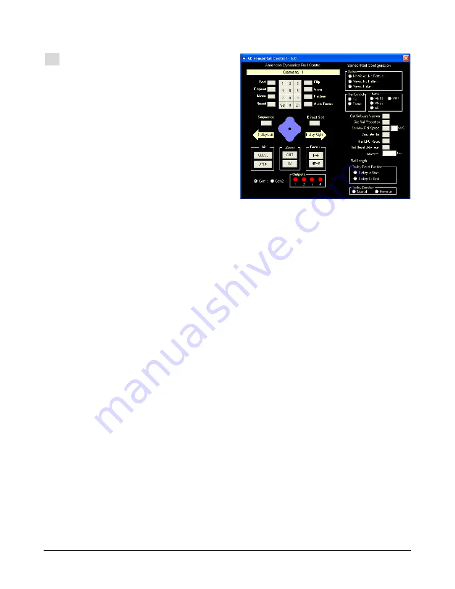
On your laptop computer, use the AD SensorRail
Control configurator screen (shown above) to test
the trolley and dome camera functions. Also, check
the entire rail for joint alignment.
To initiate the trolley for the first time:
1. Connect a DB25 to DB9 communication cable
between the laptop and the PowerRail module.
A standard crossed serial cable, wired as
shown, is required (see figure on page 31).
2. In the Power Rail module, move jumpers ST3
and ST4 to the PC position (see figure on page
31).
3. Launch the configurator application. When the
configurator screen appears, select the dome
camera address, and then press SET. For
example, if the dome address for the trolley is 9,
all commands will go to dome 9.
4. Click the CALIBRATE RAIL button on the
configurator to have the trolley learn the rail
length.
5. Using the configurator and a portable video
monitor, move the trolley along the rail to
expose possible issues, such as poor video or
trolley homing.
Note:
If RF interference is causing video
problems, try an alternate DIP switch selection
on the PowerRail. See Appendix A.
Note:
If RF holes are causing video problems,
adjust the receiving antenna’s angle and inner
position for the best compromise. If RF holes
still exist, try attaching the antenna externally to
the start end of the rail using the extension
brackets supplied. See Appendix B.


