-
1
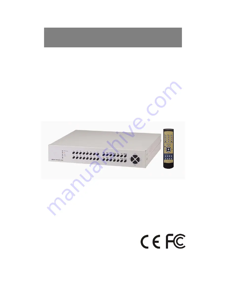
16CH Digital Video Recorder
Thank you for purchasing our product. Please read this Users Manual before using the product.
16 Channel Digital Video Recorder
V.1.0
Page 1: ...1 16CH Digital Video Recorder Thank you for purchasing our product Please read this Users Manual before using the product 16 Channel Digital Video Recorder V 1 0...
Page 2: ...exclamation point within an equilateral triangle is intended to alert the user to presence of important operating and maintenance Servicing instructions in the literature accompanying the appliance W...
Page 3: ...ON 10 3 4VCR VIDEO PRINTER CONNECTION 10 3 5NETWORK CONNECTION 11 3 6HDD CONNECTION 12 3 7POWER CONNECTION 13 4 OPERATION 14 4 1BASIC DISPLAY 14 4 2DVR SYSTEM LOG IN 16 4 3RECORDING 17 4 4PLAYBACK 20...
Page 4: ...Viewer Software MANUAL FOR REMOTE VIEWER SOFTWARE 44 1 GENERAL DESCRIPTION 44 2 TCP IPSETUPIN DVR UNIT 44 3 STATIC IPAND DYNAMIC IP 45 4 LIVE VIEW VIA IPNETWORK 47 5 SEARCH RECORDED PICTURES VIA IPNE...
Page 5: ...e place you want to install the DVR unit is stable and meets our electricity requirements Unstable electricity will cause malfunction of the unit or give critical damage to the unit 2 Several chips on...
Page 6: ...o the last of Record data when it is in stop mode 8 PAUSE pauses when it is in playback mode 9 ENTER Used as selection key in system setup or changes contents displayed in live display 10 MODE MODE re...
Page 7: ...ALARM 12 3 ALARM 3 15 GND 4 ALARM 4 16 ALARM 13 5 GND 17 ALARM 14 6 ALARM 5 18 ALARM 15 7 ALARM 6 19 ALARM 16 8 ALARM 7 20 GND 9 ALARM 8 21 RELAY OUT N O 10 GND 22 RELAY OUT N C 11 ALARM 9 23 RELAY O...
Page 8: ...auses when it is in playback mode 7 ENTER Used as selection key in system setup or changes contents displayed in live display 8 MODE MODE represents multi screen division and used to change to 4 split...
Page 9: ...nstallation 3 1 Camera Connection Connect camera to the CAMERA INPUT 1 16 on the rear panel of unit 3 2 Monitor Connection Composite monitor Connect the monitor to the MONITOR OUT on the rear panel of...
Page 10: ...10 3 3 Monitor S VHS Connection Connect S VIDEO monitor to MONITOR OUT S VHS on the rear panel of unit 3 4 VCR VIDEO PRINTER Connection Connect VCR or Video printer to VCR OUT on the rear panel of uni...
Page 11: ...d RS 485 Connected to P T Controller or Speed Dome Camera RJ 45 Connected to LAN WAN or internet Notice Teratray connection port must be used for connecting HDD Bay and can not be used for connecting...
Page 12: ...tall 2HDD HDD1 must be master and HDD2 is slave and jumper setting must be done properly as specified by HDD manufacturer Fix HDD on the bottom of DVR case using screws included in the package Screws...
Page 13: ...Press two buttons until you hear beep sound from DVR unit From next booting it is not necessary to set as above DVR system memorize video setting In the process of booting DVR system displays VIDEO SY...
Page 14: ...14 4 Operation 4 1 Basic display Turn on the power switch and DVR system shows live display from 1 to 16 as following figure DVR system already started to REC picture data automatically...
Page 15: ...C To go back to menu press MENU button while in stop mode 2 Set time when you first operate DVR unit Refer to time data setup in system setup in this manual 3 To enter into 4 spjlit 9 sjplit screen du...
Page 16: ...hen press ENTER button If password you entered is consistent with password already set PASSWORD OK is displayed and you enter into system setup if it is not system goes back to live display mode Facto...
Page 17: ...s FRZ BUTTON FRZ is displayed on top left Then press number of channel you want to freeze Picture of channel you selected is freeze picture of channel you selected freeze and F icon is displayed on th...
Page 18: ...l you can select area to be enlarged 5 PIP While you see picture of specific channel in full screen you can see small size pictures of remaining channels in rotation if you pres PIP button Time interv...
Page 19: ...of menu item B LEFT RIGHT Select command For details refer to system setup miscellaneous PAN TITL CMD setup Operation 1 Press P T BUTTON 2 Select device using buttons 3 Select command using button to...
Page 20: ...ed very similar to motion Recording 8 Cautions A When you are in system setup Recording is stopped B While DVR system is in playback mode Recording is stopped C No Recording is done in channel to whic...
Page 21: ...n represents 10 56 of total HDD space is spent for data Recording and next playback will start from the point of 5 37 of total HDD space 3 Search When DVR system is in stop mode press PLAYBACK button...
Page 22: ...an select high and low playback speed C Press FF button repeatedly to increase playback speed 1 2 4 8 16 32 64 Press FF button to decrease playback speed to 1 2 or 1 4 D You can select high speed and...
Page 23: ...automatically starts from the point of 45 in reverse direction it is for efficiency in search Record data B If you want to search Record data from the first of data press REW button in stop mode Then...
Page 24: ...ACTORY DEFAULT A Press MENU button B Enter password and log on the system C Select setup item using buttons D Press ENTER button to move to sub menu E In sub menu press buttons to move and press LEFT...
Page 25: ...to move to menu item you want to set B Enter letters using LEFT and RIGHT buttons C Move to next camera for settings using buttons D If you have same word repeated in camera title for each channel mo...
Page 26: ...of images from cameras CH NUMBER Select camera from 1 to 16 BRIGHTNESS Sets brightness 31 32 CONTRAST Adjust color contrast 31 32 SATURATION Adjust color saturation 20 32 HUE Adjust color hue 31 32 GA...
Page 27: ...27 5 4 MOTION SETUP Sets motion detection area and sensitivity of motion to be detected...
Page 28: ...ll see color of all cells inside 2 coordinates is changed to green motion detection area ALL OFF ON All cells are set as a detection area or no detection area When it is in all off press ENTER make al...
Page 29: ...29 5 5 SET TIME DATE Sets YEAR Month Day Hour Minute Second Using UP and DOWN buttons move to menu item and change value using LEFT and RIGHT buttons...
Page 30: ...n HDD is full ON Overwrite when HDD is full DEFAULT Display of RECORD SETUP RECORD SETUP RECORD TYPE OVERWRITE TIME INTERVAL EVENT OFF TIMER REFRESH RATE DURATION TIMER OFF 1 1X 60 SEC _ _ _ _ _ _ _ _...
Page 31: ...m is activated for 20sec G EVENT OFF TIMER To limit numbers of motion detected or alarm activated to be enlisted to event list we set event off timer 60 SEC Just in case time interval between previous...
Page 32: ...n HDD When HDD clear IN USE is displayed press ENTER button and input password you already set If you entered correct password HDD shall be cleared and HDD CLEAR EMPTY is displayed 2 Show information...
Page 33: ...1 BUZZER ON OFF A Press buttons to move to item you want to set and select using LEFT and RIGHT button B Press ENTER button to set To set altogether at ON or OFF move to all buzzer and set at on or of...
Page 34: ...ing is memorized by the system 3 Time interval setting Set time interval for SEQ PIP A FULL SCREEN Time interval of pictures rotating in channel sequence when SEQ button is pressed B QUAD 9 SPLIT Time...
Page 35: ...Input protocol of PTZ camera or speed dome camera which shall be controlled by data communication Via RS 485 Max length of protocol for each command is 15 byte baud rate is 9600 Max 4 PTZ cameras can...
Page 36: ...cameras from 1st to 4th DEV and input len and protocol HEX code For commands not used for your PTZ cammer len value must be set at 0 Commands whose len are 0 are not shown when you practically contro...
Page 37: ...CURRENT PASSWORD NEW PASSWORD CONFIRM PASSWORD _ _ _ _ _ _ _ _ _ _ _ _ _ _ _ _ _ _ _ _ _ _ _ _ Current password New password New password to confirm INPUT YOUR OWN PASSWORD THEN PRESS ENTER TO EXIT P...
Page 38: ...n set all groups of settings as a whole or set them group by group Move to menu items using buttons and select YES or NO and then move to RUN Press ENTER button to set at factory default for selected...
Page 39: ...to increase storage capacity connect HDD Bay to DVR unit If each of 22 HDD is 120GB in capacity total HDD capacity connected to a unit of DVR is 2 64 TG We can add huge capacity of HDD storage to a un...
Page 40: ...7MILLION SLIT SCREEN FULL QUAD 9SPLIT 16SPLIT DISPLAY ZOOM LIVE PB AVAILABLE PIP AVAILABLE SEQUENCE AVAILABLE MONITORING METHOD DISPLAY QUALITY FULL 720 H 480 V ACTIVE PIXELS FULL MOVING PICTURE 1 16S...
Page 41: ...NAL EQUIPMENT WIPER PUMP FAN AND HEATER CONFIURATION PLUG PLAY 4HDD INTERNAL1 OR 2 HDD OPTIONAL HDD BAY SUPPORT MAX 20 HDD POSSIBLE HDD MIX USGE OF DIFFERENT COMPANIES OPERATION TEMPERATURE 41F 104 5C...
Page 42: ...42 RS 232C Hex codes table Following ASCII codes are for programmers who want to control the DVR via RS 232C port 1 Byte ASCII code...
Page 43: ...43 Remote Viewer Software Thank you for purchasing our product Please read this User s Manual before using the product 16 Channel Digital Video Recorder V 1 0...
Page 44: ...ethod for access to DVR unit via Internet line and you must install Remote Viewer software included in the package on client PC before you try to access to DVR unit over IP network 2 TCP IP SETUP in D...
Page 45: ...is from the run menu Start Run and type in Command Then either hit enter or click OK At the command prompt type in ipconfig This will pull up the information that you need to find your IP Address for...
Page 46: ...and it is for your DVR unit Write down this information on separate paper and input IP Address Subnet Mask and Default Gateway into your DVR to which you want to access via IP network d Confirm if IP...
Page 47: ...uit Before press power switch button press disconnect button first 2 Connect button Press connect button to connect to DVR unit via IP network to see live pictures of DVR unit You will see the same li...
Page 48: ...u will see channel number from 1 to 9 are all activated Channel number button You can select channel number to see live pictures from selected channel Status window It shows Date and Time Further it d...
Page 49: ...rcular monitoring interval is The absolute circulation interval is a little different from set value depending on data transfer rate of IP network vSelect scan rate ranging from 1x to 64x The larger i...
Page 50: ...Command Save the current command value Delete PT Command Delete the command which you selected Load user PT File Load the PT command File Save user PT File Save the All PTZ command to a file dLength S...
Page 51: ...trol You can control Zoom Focus and Pan Tilt of PTZ camera while you see live pictures via IP network Of course you must input PTZ command for a specific PTZ camera you connected to your DVR unit into...
Page 52: ...first chose full screen button 2 7 Time selection button You can set time to search by dragging yellow mover to the left or right See time displayed in green color and find an exact time from which yo...
Page 53: ...e download page of our home page www amebacctv com Notice Compatibility of Remote Viewer Software with different kinds of operating systems and PC hardware may not be simply specified due to the chara...