


Unscrew the fixing screw in the housing lid
and remove.
Remove pressure test point screw nearest
the burner head and connect a ‘U’ tube
manometer to the pressure test nipple
located on the body of the gas valves.
Remove the slotted cover from the pressure
test regulator revealing the adjustable screw.
Replace mains input connector and start the
heater. Using a suitable screwdriver adjust
the pressure regulator. Switch off the
heater by pulling out the mains input
connector. Disconnect ‘U’ tube manometer
and refit screw in pressure test nipple.
If heater is flued check that there is
adequate up draught at the down draught
diverter e.g. by means of a smoking taper
when heater is running. Check the
operation of the flame safe guard
equipment as follows. With the heater
running normally, switch off the gas supply
at the appliance isolating valve.
Check the operation of the vacuum proving
switch as follows. With the heater running.
Observe that the ‘burner on’ lamp
extinguishes within one second. After a
purge period of approximately 9 seconds
the heater should attempt to re-light and if
the gas isolating valve has been left off, lock
out should occur indicated by power light
only being illuminated and fan running.
Check the operation of the vacuum proving
switch as follows. With the heater running
normally pull out the three pin fan
connection plug, thus causing the fan slow
down and stop. Within 3 seconds the
burner should shut off.
Observe for at least 20 seconds that there is
not attempt to re-ignite , then replace the
three pin plug and observe that the heater
proceeds to ignite in the normal way.
Close the safety control housing lid which is
secured with the fixing screws.
Figure 8
Figure 9
Figure 10
8
Hand the ‘User Instructions’ to the user and
explain how to operate the heater.
Leave the ‘Installation and Servicing
Instructions’ at the users meter or preferably
with the service / maintenance engineer /
manager for use on future service calls.
Note It will be noted that heaters have a
tendency for the U bend to glow. This is
normal and quite acceptable.
Frequency of servicing
The manufacturer recommends that to
ensure continued efficient and safe
operation of the Vision Compact it is
recommended that the heater is serviced
regularly by a competent person e.g every
year in normal working conditions but in
exceptional dusty or polluted conditions
more frequent servicing may be required.
The manufacturer offers a maintenance
service. Details are available on request.
Tools required for servicing
The tools required to carry out any servicing
of the Vision Compact range of heaters are
as follows 4mm allen key; electrical screw-
driver; 13mm spanner; 10mm spanner;
8mm spanner; cross head screwdriver;
adjustable spanner; pipe wrench; soft bristle
brush; and a soft cloth.
Recommissioning after service
After servicing of the heater has been
completed it will be necessary to
recommission the heater as outlined in the
relevant section of the instructions.
soft brush. Similarly remove any dust from
the finger guard covering the secondary
(cooling) impeller and the mesh aperture in
the motor cover. Ensure that the impeller
turns freely and that there is no excessive
play in the bearings. Do not replace fan
until emitter tube inspection has been
completed.
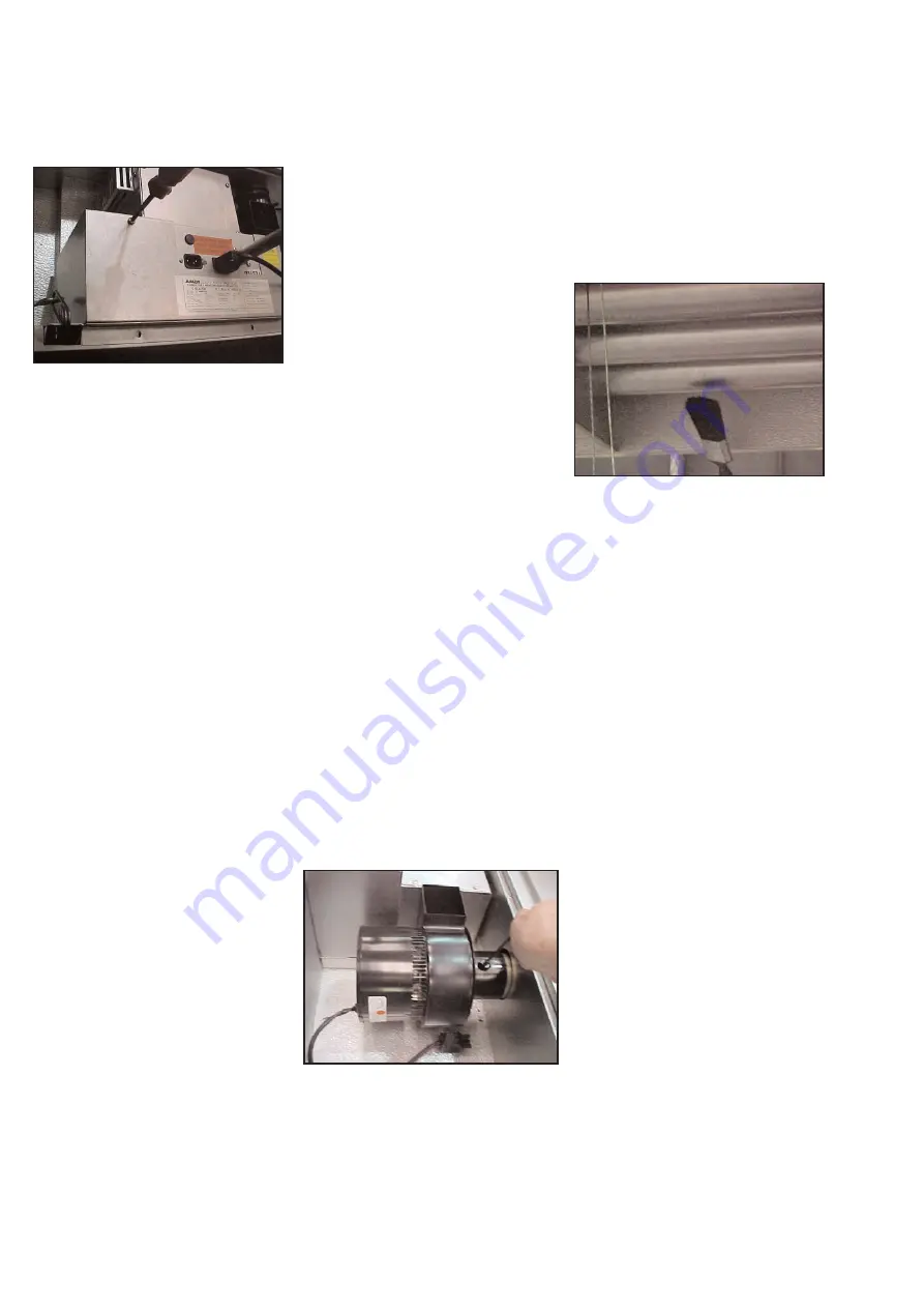
ID fan
Remove ID fan by unplugging the electrical
connection from the burner / control
assembly and loosening the fan securing
pinch screw. If a flue is fitted, this must be
disconnected. The fan will now slip off the
emitter tube. Inspect the main fan impeller
and remove any dust by brushing with a
Emitter tube inspection
Brush away any dust on the exterior of the
emitter tubes.
Access to the firing and return leg, tubes
can be achieved by removing the outer
panel at the burner end.
Remove the burner assembly and ID fan.
Through the two access holes in the inner
panel view down the tubes and if carbon
deposits are evident clean out with a
suitable rod.
Although not considered necessary on
routine service, if heavy carbon deposits are
present, it maybe necessary to clean down
all the tubes. To do this, remove the
reflectors tube clamps and burner assembly.
Take the tube assembly out of the product
and by removal of each leg and turbulator
(where fitted) clean out the tubes and re-fit.
Access to the firing and return leg, tubes
can be achieved by removing the outer
panel at the burner end.
Inspect the emitter tubes internally. If there
is any appreciable build up of dust or
deposits the tubes should be cleaned
internally. Remove the burner / control
assembly as directed.
13 Routine service
Reflector
It is recommended that the top of the
reflector is cleared of any dust annually and
or before the start of each heating season.
The condition of the reflector should be
noted and the users attention drawn to any
cleaning necessary. The reflector can be


