


Product description
4
4.1
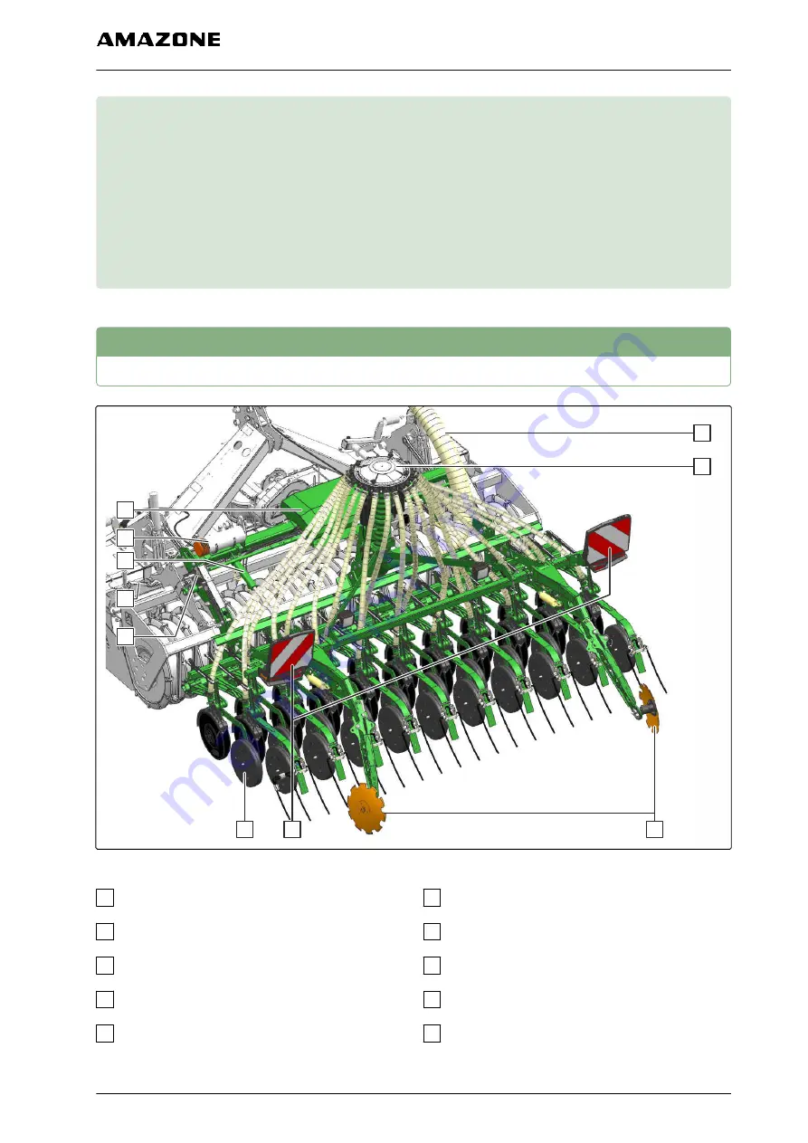
Implement overview
1
2
3
4
5
7
6
8
9
10
CMS-I-00003585
1
Conveyor hose
2
Distributor head
3
Tramline marker
4
Rear-facing lighting
5
TwinTeC double disc coulter
6
Placement depth adjustment device
7
Universal operating tool on carrying implement
8
Coulter pressure adjustment device
9
Threaded cartridge
10
Job computer
CMS-T-00004877-A.1
CMS-T-00004883-A.1
4 | Product description
MG6860-EN-II | A.1 | 20.07.2020
23
Summary of Contents for TSE 3000
Page 1: ...Operating manual MG6860 EN II A 1 20 07 2020 seeding rail TSE 3000 Original operating manual...
Page 96: ......
Page 97: ......


