background image

NITID N26_N36_N46

Oct 2017

19

Amate Audio

Delay

0.0ms

0.0m

Delay

35.3ms

12.0m

GR (Gain Reduction): This bar shows when the limiter is active (the threshold
value  is  being exceeded by  the  input  level).  The  gain  reduction  level  will
display as an inverted VU bar (see Fig. 20, right).

OUT:  output  level  after  the  limiter.  This  is  the  actual  signal  level  after  the
signal  goes  through  the  limiter.  If  the threshold is  not  reached,  it  will  be  the
same as the input level. If the threshold is exceeded, there will be a reduction.

The  limiter  acts  over  the  Peak  limiter  value.  The  system  has  also  an
internal RMS limiter that is fixed (see Section 4.7.1).

4.4.4. Delay Menu

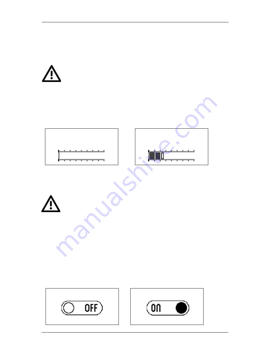
In  the  Delay  Menu,  it  is  possible  to  add  a  Delay  to  the  signal  in  the  internal  DSP.
Press OK to start editing the Delay value. The cursor will blink to show that the value
is  being  edited.  Use  the  Circular  key  to  modify  the  value,  and  press  OK  to  finish
editing.

The value of the Delay is displayed in milliseconds (ms) and meters (m). The value
of the delay ranges from 0 to 40 meters (0 to 117.6ms).

The delay value is applied short after a value has been selected with the
Circular  key.  When  the  delay  is  applied  a  short  fade  in  /  fade  out  of  the
output signal will be performed.

The center led of the circular key will light off while this process is performed, and will
light on again when the new value has been loaded.

4.5.

SETUP Menu

When the word SETUP is displayed, press OK. The ECO Mode on/off selection will
show up as in Fig. 22.

Here,  use  the  MENU  key  to  browse  all  the  setup  options:  ECO  Mode,  Front  Led,
Front Limiter Indication, Mute, Loudness (ALC), LCD Backlight and Keypad Lock.

Press OK to change the value for the displayed selection (switch between ON/OFF).

ECO Mode

ECO Mode

Fig. 21.

Delay display (left) and Delay while editing (right)

Summary of Contents for N26

Page 1: ...User s manual October 2017...

Page 2: ...wer cord from being walked on or pinched particularly at plugs convenience receptacles and the point where they exit from the apparatus 10 The equipment must be repaired by qualified technical service...

Page 3: ...em XLR electronically balanced input XLR parallel output AC PowerCon input and link 500 W Class D amplifier for low mid range 100 W Class D amplifier for high range 24 bit AD DA converters 48 kHz samp...

Page 4: ...ts on N26 N36 N46 The N26 N36 and N46 include several manufacturer presets for different types of applications FLAT Flat response NEARFIELD 3dB mid frequencies 400Hz 4 kHz LONGTHROW 3dB high frequenci...

Page 5: ...he DSP such as Preset selection audio settings and user preferences There are three keys available MENU key OK key Circular key To enter the menu the keypad must be unlocked by pressing simultaneously...

Page 6: ...he amplifier is delivering the maximum power set by the limiter circuit The limiter prevents the loudspeaker from receiving excessive or distorted signal Continuous lightning of this led indicates tha...

Page 7: ...in parallel Linking up to 10 units is possible provided that a quality cable of a minimum section of 3x2 5mm2 is used Connecting more than 10 units in parallel may lead to a voltage drop in the cable...

Page 8: ...NITID loudspeakers or subwoofers in parallel with N26 N36 or N46 Please follow the same parameters as explained in Fig 2 3 MOUNTING AND PLACEMENT For a proper installation of the acoustic cabinet sys...

Page 9: ...crew the horn again and finally place the frontal grille in its right position Good coverage of audiences often is a conflicting combination of wide coverage for the closest audience short throw narro...

Page 10: ...ed Cabinets Flown and aiming to the audience We need wide coverage 100 for the closest listeners and narrow coverage for the distant audience Fig 5 Vertical position 3 3 2 Horizontal Positioned Cabine...

Page 11: ...the load bearing capabilities of the structures where the cabinets will be placed Hanging hardware as chains eyebolts lock pins should be regularly inspected and replaced if in doubt DO NOT SUSPEND T...

Page 12: ...dels provide several M8 flying points Their correct use will permit the flying in horizontal or vertical position Fig 9 N26 rigging points N26 Horizontal flying 3 7 or 4 8 or 1 9 or 2 10 front rigging...

Page 13: ...or 2 10 front rigging points 5 6 back tilt points Vertical Flying 1 2 or 3 4 front rigging points 5 or 6 back tilt points 3 5 3 N26 horizontal flying with U BL The UB L is an optional accessory for w...

Page 14: ...N46 vertical flying with HR bar Use HR C or HR C GT flying bar for vertical flying Refer to HR C instructions manual and HR C GT instructions manual for more information Fig 12 HR C flying bar for N2...

Page 15: ...ctive cabinets can be configured for different applications This section explains all the possible configurations The LCD and keypad on the cabinet s back panel are used for the setup The available ke...

Page 16: ...the main menus The first option displayed will be PRESETS Press MENU again to browse the different available menus as following PRESETS To change the factory preset of the DSP AUDIO To change differe...

Page 17: ...the value Slide finger clockwise to increment the value Circular key Center blue ring is illuminated when they key is active Counter clockwise to decrement the value An asterisk beneath the preset na...

Page 18: ...display Press OK to start editing the EQ Low left bar The cursor will blink to show that the value is being edited Use the Circular key to modify the value At this point use the MENU key to change bet...

Page 19: ...ill blink to show that the value is being edited Use the Circular key to modify the value and press OK to finish editing The value of the Delay is displayed in milliseconds ms and meters m The value o...

Page 20: ...ECO Mode is ON the system will continuously analyse the input signal When no input signal is present after 1 minute the system will go in a low power consumption mode standby This condition will be in...

Page 21: ...amically adapt the frequency response of the cabinet to the listening conditions This feature will only influence the frequency response when the input signal average is below 6dB of the nominal input...

Page 22: ...highlight the option Restore Then press OK to confirm Audio Settings 1 Preset FLAT Gain 0 00dB Gain LF 0 00dB Gain HF 0 00dB Delay 0 0m Limiter 0 00dB Audio Settings 2 Mute OFF EQ LOW 0 00dB EQ M LOW...

Page 23: ...amplifier s heatsink the system will shut down in Protection mode 4 7 3 Input Overload Protection NITID systems have a nominal input voltage of 8dBu 2V 2dBu 1V in subwoofers for full power performance...

Page 24: ...48 bit Built in delay line 118 ms 40 m Audio Performance Frequency response 10 dB usable bandwith 58 Hz 20 kHz 53 Hz 19 kHz 50 Hz 19 kHz SPL 1m 121 dB continuous 124 dB peak 123 dB continuous 126 dB...

Page 25: ...NITID N26_N36_N46 Oct 2017 25 Amate Audio Note Specifications subject to change without notice...

Page 26: ...lona SPAIN by Amate Audio S L Perpiny 25 Pol gon Industrial Nord 08226 Terrassa T 34 93 735 65 65 F 34 93 735 60 48 info amateaudio com R D and FACTORY Violinista Vellsol 18 08222 Terrassa T 34 93 736...

Reviews: