8
Operating pressures and current draw can also be com-
pared with the data given in the “Specification Sheet”. If
the system is performing properly, reinstall the service port
caps and the valve bonnets. With the valve opened, the
valve bonnet is the primary seal against refrigerant leaks.
See the table below for the torque required for an effective
seal on the valve bonnet (1/6 turn past finger tight).
Tubing Size
Torque (Foot-Pounds)
3/8
10
1/2, 5/8, 3/4
14
7/8, 1 1/8
16
After closing the valve bonnet, perform a final refrigerant
leak test on the valves and sweat connections. Return the
room thermostat to the desired settings.
TROUBLESHOOTING
(QUALIFIED SERVICE TECHNICIAN ONLY)
When troubleshooting, the first step should always be to
check for clean coils, clean filter(s), and proper airflow.
Indoor airflow should be 350 to 450 CFM per ton of cooling,
based on the size of the outdoor unit. The most common
way of establishing indoor airflow is heating temperature
rise. Indoor airflow will then be (Heating output of equip-
ment) / (1.1 x temp. rise). In other cases, measurement of
external static pressure is helpful. For details, see the
Installation Manual for your indoor equipment.
If further information is needed, see the Remote Heat
Pump Service Manual.
V. Defrost System
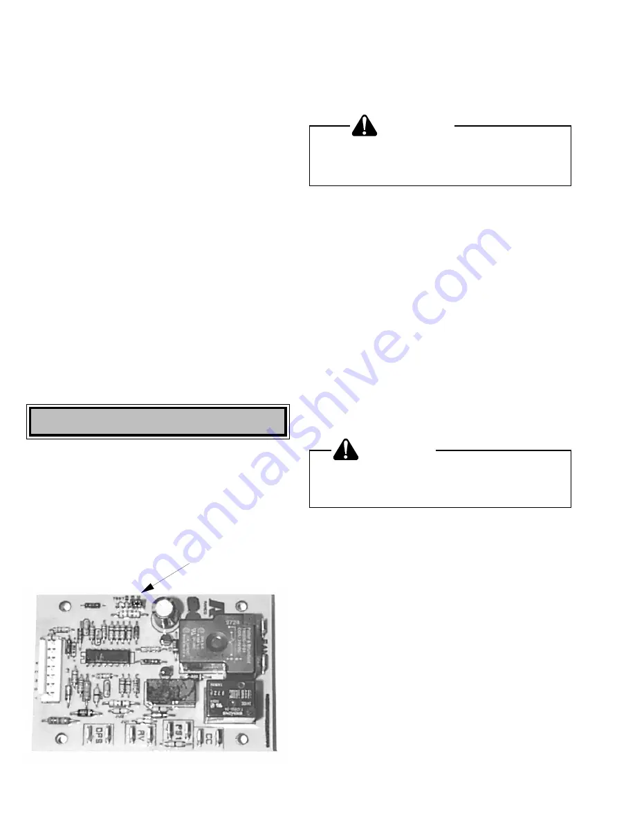
The RHA**B2A models are equipped with a time tempera-
ture type defrost board. Defrosting of the OD coil is
determined by both coil temperature and compressor run
time. See the “Specification Sheet” for factory settings.
Adjustment can be changed as required. There are 30, 60,
and 90 minute settings available. Adjust only if geographi-
cal conditions, outdoor humidity, or other adverse condi-
tions make it necessary.
DEFROST TIME ADJUSTMENT PIN
Figure 5
NOTE: If the time select pin remains in test position for 5
minutes, the control will ignore test mode and assume a
normal 90 minute defrost cycle. To over ride this time out,
remove the select pin briefly and replace back on test.
WARNING
To avoid electrical shock or death,
disconnect the power before changing the
defrost time cycle.
If adjustment of the run time appears advisable:
1. Disconnect power to OD unit.
2. Move the defrost time adjustment pin from 90 minutes
to 60 minutes or 30 minutes as required (refer to
Figure 5).
3. Reconnect the electrical power.
The maximum defrost time is 14 minutes. Most defrost
cycles are shorter.
SERVICING: When servicing, it may be necessary to
rapidly advance the system through a defrost cycle. To do
this:
Place the defrost time adjustment pin on Test. When the
unit starts the defrost cycle, quickly remove the time select
pin to allow normal defrosting and defrost termination to
proceed. The select pin may be reconnected to test or
repeat the defrost cycle, or the pin may be placed in the
desired time setting. (Jumping both test pins with a small
insulated screw driver will also work.)
WARNING
To avoid electrical shock or death,
disconnect the electrical power before
servicing.


