background image

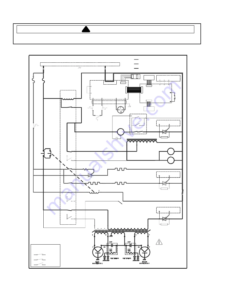
60 Hz Troubleshooting Procedures 

!

WARNING

To avoid risk of electrical shock, personal injury or death; disconnect power to oven and discharge capacitor  
before servicing, unless testing requires power. 

12


16023463 

©2006 Maytag Services


Cook Condition

208

INTERLOCK SWITCH SCHEMATIC

DOOR CLOSED

2

4

7

3  SECONDARY

SCHEMATIC CONDITION: DOOR CLOSED

5  PRIMARY

8  MONITOR

    DANGER

HIGH VOLTAGE

M1

UPPER

SWITCH

J4

J8-7

J6

J3- 3

J2- 3

J2- 4

7

8

L2

GND

L1

INTERLOCK

(SECONDARY)

SNUBBER

J7-2

J7-1

SNUBBER

J7-5

SNUBBER

J7-4

J7-3

G

G

G

T1

T2

T1

T2

T2

TRIAC (TR3)

MAGNETRON

(LEFT)

TRIAC (TR2)

HEATER

(M IDDLE)

TRIAC (TR1)

BLOWER

(RIGHT)

POWER BOARD

DISPLAY
BOARD

208/230V 60HZ

CONVECTION HEATER

(REAR)

DO NOT REMOVE WIRE FROM TRIAC TERMINAL
T2 DURING TESTING. THIS WILL CAUSE
HV BOARD TO SHORT OUT.

CAUTION:

M2

RTD

5

J8-4

J8-6

SHIELDED

  CABLE

4

J1-1

J1-3

J8-3

E1

E2/E3

POWER

BOARD

POWER

BOARD

POWER

BOARD

POWER BO ARD

DOOR

INTERLOCK

(PRIMARY)

LOWER

SWITCH

J5

J5

J4- 1

J8-2

J8-1

COM

MAG 1

TCO

RADIANT HEATER

(RH)

230

POWER TRANSFORMER

MAG 2

TCO

25A

HEATER

FUSE 2

25A

MAG

FUSE 1

CAPACITOR

208

120

AUTO TRANSFORMER

M3

STIRRER

COM

230

CURRENT

SENSE

0

POWER RELAY COIL

8

6

4

2

2

3

J4- 3

K9 

(208)

K8 

(230)

NO

NO

NC

K7

NO

NC

NO

NC

K5 

(230)

NO

NO

K4 

(208)

J3- 1

J4- 7

J1- 2

J2-1

J2- 5

K1

J4- 6

COOLING FAN

CONVECTION FAN

INTERLOCK

(M ONITO R)

E4

T1

CONTROL

TCO

NO

K2

NO

NO

J4-5

TEMP

LIMITER

J1-1

(LH)

J2-2

J4- 2

J4- 4

E6

E7

POWER

RELAY

K6

K3

E5

SPEAKER

BOARD

J2-1

J2-2

J2-4

J1-4

J1-2

J1-1

 CONTROL/TEMPERATURE

 CONVECTION  (FUSE 2)

 MICROWAVE   (FUSE 1)

SNUBBER

J7-1

J7-6

J7-5

J7-3

G

G

G

E5

RLY1

RLY2

RLY1

RLY2

NC

NO

NC

NO

E2

NO

RADIANT HEATER

360   ½ W
RESISTOR


DATA KEY

BOARD

J6

P1

P2

HALFWAVE

PROTECTION

BOARD

Summary of Contents for AMH20

Page 1: ...sed by qualified appliance technicians only Maytag does not assume any responsibility for property damage or personal injury for improper service procedures done by an unqualified person 16023463 November 2006 60 HZ Models AMH20 P1330801M AMH202 P1331101M AMH20D P1332501M JBH202 P1331102M SZH20 P1331104M 50 HZ Models AMH20A2 P1331103M AMH20AD2 P1332504M P1332506M MMH20AD2 P1332505M P1332507M C O M...

Page 2: ...EVIEW ALL APPROPRIATE SERVICE INFORMATION BEFORE BEGINNING REPAIRS WARNING To avoid risk of severe personal injury or death disconnect power before working servicing on appliance to avoid electrical shock To locate an authorized servicer please consult your telephone book or the dealer from whom you purchased this product For further assistance please contact Service Support Center Contact your lo...

Page 3: ...26 Magnetic Door Stop 26 Outer Door 26 Inner Door Assembly 26 Hinge 26 Outer Case 27 Back Panel 27 Interlock Switch Module 27 Stirrer Motor and Antenna Gears 27 RTD Resistance Thermal Device 28 Top Touch Panel Assembly 28 Table of Contents Side Touch PanelAssembly 28 Display Module 28 Heating Elements oven top 28 Inlet Duct Assembly 28 Halfwave Board 28 Control Board Assembly Bracket 29 High Volta...

Page 4: ... 14 If servicer encounters an emission reading over 4mw cm2 the servicer is to cease repair and contact the Amana Service Department immediately for further direction Amana Manufacturing will contact the proper Government Agency upon verification of the test results 1 Always operate the unit from an adequately grounded outlet Do not operate on a two wire extension cord 2 Before servicing the unit ...

Page 5: ...y qualified service personnel Special tools are required to service equipment Contact nearest authorized service facility for examination repair or adjustment 10 DO NOT cover or block filter or other openings on equipment 11 DO NOT store this equipment outdoors DO NOT use this product near water for example near a kitchen sink in a wet basement or near a swimming pool and the like 12 DO NOT immers...

Page 6: ...hat are not intended for cooking 11 When cooking with paper plastic or other combustible materials follow manufacturer s recommendations on product use 12 Do not use paper towels which contain nylon or other synthetic fibers Heated synthetics could melt and cause paper to ignite 13 Do not heat sealed containers or plastic bags in oven Food or liquid could expand quickly and cause container or bag ...

Page 7: ...wed Grounding Instructions WARNING Do not remove grounding prong when installing grounded appliance in a home or business that does not have three wire grounding receptacle under no condition is grounding prong to be cut off or removed It is the personal responsibility of the consumer to contact a qualified electrician and have properly grounded three prong wall receptacle installed in accordance ...

Page 8: ...t This information was written for those who do not understand grounding and polarization of a wall outlet A 208 230 volt wall outlet must always be wired as shown below Neutral N This slot is the larger of the two and should be neutral dead with respect to ground Hot H This slot is the smaller size and should always be hot live with respect to neutral N and ground G Ground G The round hole connec...

Page 9: ...may cause interference to radio television or similar equipment Reduce or eliminate interference by doing the following Clean door and sealing surfaces of oven according to instructions in Care and Cleaning section Place radio television etc as far as possible from oven Use a properly installed antenna on radio television etc to obtain stronger signal reception Model Identification For Amana produ...

Page 10: ...LDED CABLE 4 J1 1 J1 3 J8 3 DOOR INTERLOCK PRIMARY LOWER SWITCH J5 J5 J4 1 J8 2 J8 1 COM MAG 1 TCO RADIANT HEATER RH 230 POWER TRANSFORMER MAG 2 TCO 25A HEATER FUSE 2 25A MAG FUSE 1 CAPACITOR REAR MAGNETRON 2 FRONT MAGNETRON 1 208 120 AUTO TRANSFORMER M3 STIRRER COM 230 CURRENT SENSE 0 POWER RELAY COIL 8 6 4 2 2 3 J4 3 K9 208 K8 230 NO NO NC K7 NO NC NO NC K5 230 NO NO K4 208 J3 1 J4 7 J1 2 J2 1 J...

Page 11: ... RTD 5 J8 4 J8 6 SHIELDED CABLE 4 J1 1 J1 3 J8 3 POWER BOARD POWER BOARD DOOR INTERLOCK PRIMARY LOWER SWITCH J5 J5 J4 1 J8 2 J8 1 COM MAG 1 TCO RADIANT HEATER RH 230 POWER TRANSFORMER MAG 2 TCO 25A HEATER FUSE 2 25A MAG FUSE 1 CAPACITOR REAR MAGNETRON 2 FRONT MAGNETRON 1 208 120 AUTO TRANSFORMER M3 STIRRER COM 230 CURRENT SENSE 0 POWER RELAY COIL 8 6 4 2 2 3 J4 3 K9 208 K8 230 NO NO NC K7 NO NC NO...

Page 12: ... TESTING THIS WILL CAUSE HV BOARD TO SHORT OUT CAUTION M2 RTD 5 J8 4 J8 6 SHIELDED CABLE 4 J1 1 J1 3 J8 3 E1 E2 E3 POWER BOARD POWER BOARD POWER BOARD POWER BOARD DOOR INTERLOCK PRIMARY LOWER SWITCH J5 J5 J4 1 J8 2 J8 1 COM MAG 1 TCO RADIANT HEATER RH 230 POWER TRANSFORMER MAG 2 TCO 25A HEATER FUSE 2 25A MAG FUSE 1 CAPACITOR 208 120 AUTO TRANSFORMER M3 STIRRER COM 230 CURRENT SENSE 0 POWER RELAY C...

Page 13: ...rocedures W ARNING To avoid risk of electrical shock personal injury or death disconnect power to oven and discharge capacitor before servicing unless testing requires power 2006 Maytag Services 16023463 13 Stand By Condition ...

Page 14: ...rocedures W ARNING To avoid risk of electrical shock personal injury or death disconnect power to oven and discharge capacitor before servicing unless testing requires power 14 16023463 2006 Maytag Services Pre Heat Condition ...

Page 15: ... Procedures W ARNING To avoid risk of electrical shock personal injury or death disconnect power to oven and discharge capacitor before servicing unless testing requires power 2006 Maytag Services 16023463 15 Cook Condition ...

Page 16: ...itor terminals and connect ohmmeter set on highest resistance scale to terminals Also check between each terminal and capacitor case Between Terminals Meter should momentarily deflect towards zero then return to over 5 M If no deflection occurs or if continuous deflection occurs replace capacitor Terminal to Case Infinite resistance Snubber assembly Disconnect wires to snubber Measure resistance a...

Page 17: ...er Discharge Capacitors Remove all wires from terminals Measure resistance from 230 V to 0 V 208 V to 0 V 120 V to 0 V Approximately 38 Approximately 37 Approximately 25 7 8 2 4 3 5 Interlock switch Door Closed 2 4 7 3 5 8 Primary Secondary Monitor Disconnect wires to switch With door open measure resistance Terminal 2 to 3 Terminal 4 to 5 Terminal 7 to 8 With door closed measure resistance Termin...

Page 18: ...AVE HIDDEN PAD HIDDEN PAD THEN TEMP ENTRY Side touch panel Continuity is 100 and below Pad 1 2 3 4 5 6 7 8 9 0 Start Stop Reset Trace measure both 3 1 5 1 3 1 6 1 3 1 7 1 3 1 8 1 3 1 9 1 4 1 5 1 4 1 6 1 4 1 7 1 4 1 8 1 4 1 9 1 5 1 6 1 6 1 9 1 Measurement Continuity Continuity Continuity Continuity Continuity Continuity Continuity Continuity Continuity Continuity Continuity Continuity Top touch pan...

Page 19: ...ment Results K1 Cooling Conv fan Volts E2 Red wire E4 Black wire Test mode pad 1 off No voltage Test mode pad 1 on Voltage K2 Heater Top RH LH Volts E2 Red wire Back terminal on Heating Element Hinge Side Violet wire Test mode pad 2 off No voltage Test mode pad 2 on Voltage K3 Convection heater Volts E2 Red wire Convection Heating Element Gray wire Test mode pad 4 off No voltage Test mode pad 4 on...

Page 20: ... Procedure 1 Fill the test container to the 1000 ml line with cool tap water NOTE Water temperature should be approximately 60 F 16 C 2 Using the thermometer stir water for five to ten seconds measure and record the temperature T1 3 Place test container of water in the center of oven cavity using the lowest rack position and close door 4 Heat the water for a 33 second full power cycle by using the...

Page 21: ...xample LOW HIGH Cycle 1 230 C 240 C Cycle 2 230 C 240 C 460 C 480 C 940 C 940 C 4 230 C average temperature If the average temperature is too high or too low the oven temperature offset needs to be calibrated Convection Temperature Calibration NOTE It is normal for the average oven temperature to vary from the oven setting by as much as 14 C 25 F Difference will not effect cooking since recipes ar...

Page 22: ...odes NOTE Before scheduling service for any error codes instruct customer to unplug oven for 1 minute reconnect power and retest If unit operates properly no service call is required Display Description Corrective Action Err1 Checksum failure Replace Power Board Err2 Hardware problem Replace Power Board Replace Keyboard Err3 Hardware problem Replace Power Board Replace Keyboard Err4 Wrong jumper s...

Page 23: ...ice Test Putting the oven into Service Test allows you to individually diagnose individual components of the oven as well as access the Tube Hours and Door Cycles the oven has experienced Entering Service Test Step Action Display Description 1 LEVEL Turn OFF oven by Pressing PREHEAT ON OFF 2 LEVEL Press HIDDEN PAD 3 STG indicates input power is 230 VAC QTY indicates input power is 50 Hz LEVEL Pres...

Page 24: ... Pad Press pad once to turn on Press again to turn off On Pads 2 3 counter will count up to 62 seconds then output will turn off LEVEL Convection Fan Internal Cooling Fan runs also to prevent unit from overheating LEVEL Radiant Heater Convection Fan runs also to prevent unit from overheating LEVEL Magnetrons Internal Cooling Fan runs also to prevent magnetrons from overheating LEVEL Convection Hea...

Page 25: ...ath disconnect power to oven and discharge capacitor before servicing unless testing requires power 2006 Maytag Services 16023463 25 Action Display Description LEVEL Mag Hours 241 shown in this example LEVEL Door Cycles 13 895 shown in this example 0 LEVEL Displays OFFSET temperature ...

Page 26: ...ress door against oven on the hinge side and tighten side hinge mounting screws in the sequence shown below 1 2 3 4 Magnetic Hinge Cover Door Handle Remove door handle by removing plastic plugs to gain access to set screws Loosen set screws using a 3 32 inch allen screws one located to the left of the door handle and one located on the bottom of the door handle Pointed tip Flat tip Plastic plugs T...

Page 27: ... Remove mounting screws securing interlock switch 5 When replacing assembly all wires must be connected before operating oven NOTE When the line fuse is blown interlock switch module must be replaced 7 8 2 4 3 5 Adjustment 1 To adjust interlock switch assembly close door 2 Loosen bottom and top screw on the interlock switch assembly allowing switch assembly to move in or out 3 With door closed pus...

Page 28: ...y 1 See Component Location Figure 1 page 32 2 Remove outer case see Outer Case procedure 3 Disconnect all wire connectors and ribbon cables from display board 4 Remove screws securing top touch panel to unit 5 Remove screws securing display board to top touch panel assembly 6 Reverse procedure to reassemble Side Touch Panel Assembly 1 See Component Location Figure 1 page 32 2 Remove outer case see...

Page 29: ...mer 3 Remove screws securing auto transformer to power assembly bracket 4 Reverse procedures to reassemble Triacs Figure 3 Page 33 1 Remove back panel see Back Panel procedure page 33 2 Disconnect and label wire terminals from selected triac 3 Remove screws securing triac to power assembly bracket 4 Reverse procedures to reassemble Power Relay Figure 3 Page 33 1 Remove back panel see Back Panel pr...

Page 30: ...assemble Microwave Blower Wheel and Motor 1 Remove blower bracket assembly see Blower Bracket Assembly procedure also see figure 7 2 Remove screws securing blower assembly to bracket 3 Loosen allen set screw securing blower wheel to motor shaft 4 Remove blower wheel 5 Remove screws securing motor to scroll 6 Reverse procedure to reassemble NOTE When reinstalling blower wheel push blower wheel on s...

Page 31: ...e 2 Remove screws securing convection element to convection box 3 Reverse procedure to reassemble NOTE Center convection element around convection fan blade and spin fan blade to ensure it does not hit convection element Thermal Limiter 1 See figure 3 page 33 for location 2 Remove outer case see Outer Case procedure 3 Disconnect and label wire terminals from limiter 4 Remove screws securing therma...

Page 32: ...tors before following any disassembly procedure WARNING 32 16023463 2006 Maytag Services Component Location Figure 1 Touch Panels Displays Triacs Figure 2 Heating Element Assembly Heating Elements Retainer Clips Plenum Plate Plenum Cavity Calrod Blocks Set Screw Touch Panel Top Touch Panel Side Guide Racks Display Module ...

Page 33: ...ces 16023463 33 Figure 3 Overview Speaker Board Interlock Assembly Power Cord Magnetrons H V Transformer Blower Capacitors Diodes Inlet Duct Assembly Thermal Limiter RTD Temperature Sensor Exhaust Duct Convection Motor Halfwave Board 60 Hz Models Line Filter 50 Hz Models Auto Transformer 60 Hz Models Line Filter 50 Hz Models Power Relay Triacs Convection Motor Capacitor Magnetron Inlet Cover ...

Page 34: ...sembly procedure WARNING 34 16023463 2006 Maytag Services Figure 5 HeaterAssembly Torque to 30 in lbs while holding fan blade stationary Fan Blade Convection Element Convection Box Convection Motor TCO Control Figure 4 AntennaAssembly Control TCO Antenna Motor Gears Retainer Clips Antenna Motor Gears Retainer Clips Earlier Production Later Production ...

Page 35: ... 2006 Maytag Services 16023463 A 1 Appendix A ...

Page 36: ...ownership be sure this manual accompanies equipment Owner s Manual Contents Model Identification 2 PRECAUTIONS TO AVOID POSSIBLE EXPOSURE TO EXCESSIVE MICROWAVE ENERGY 2 IMPORTANT SAFETY INSTRUCTIONS 3 Grounding Instructions 5 Installation 5 Display and Features 6 Cooking and Toasting 9 Care and Cleaning 12 Service Codes 13 Troubleshooting 13 ...

Page 37: ...llation _________________________ Dealer s name and address __________________ ________________________________________ ________________________________________ PRECAUTIONSTOAVOIDPOSSIBLEEXPOSURE TOEXCESSIVEMICROWAVEENERGY A DO NOT attempt to operate this oven with the door open since open door operation can result in harmful exposure to microwave energy It is important not to defeat or tamper wit...

Page 38: ... burns 11 DO NOT operate this equipment if it has a damaged cord or plug if it is not working properly or if it has been damaged or dropped 12 This equipment including power cord must be serviced ONLY by qualified service personnel Special tools are required to service equipment Contact nearest authorized service facility for examination repair or adjustment 13 DO NOT cover or block any openings o...

Page 39: ...ls follow manufacturer s recommendations on product use 10 Do not use paper towels which contain nylon or other synthetic fibers Heated synthetics could melt and cause paper to ignite 11 Do not heat sealed containers or plastic bags in oven Food or liquid could expand quickly and cause container or bag to break Pierce or open container or bag before heating 12 Racks utensils rack guides and oven s...

Page 40: ...ound oven cools electrical components With restricted air flow oven may not operate properly and life of electrical parts is reduced B Install combination oven so oven bottom is at least 3 feet 91 5 cm above floor Oven Clearances To avoid risk of electrical shock or death this oven must be grounded and plug must not be altered Grounding Earthing Instructions Oven MUST be grounded Grounding reduces...

Page 41: ... the oven is not at preheat temperature NOT flashes while the oven heats to preheat temperature Display A Oven Door Handle Lift to open B Door Shield C Top Control Panel D Display E Side Control Panel If Item is not displayed keypad will not accept entries To activate keypad open and close oven door Item will then display Preheat ready displays when oven has reached the preset preheat temperature ...

Page 42: ...ction C and microwave energy M are used Cook level displays with the amount of microwave energy used Displays when changing fan setting Press and hold POWER LEVEL to display Displays stage the oven is cooking in during multi stage cooking programs Convection cooking only Displays programmed ITEM digit pad selected by user Displays when changing heater setting Press and hold TEMP ENTRY to display T...

Page 43: ...ower level HI is the highest setting and 0 is lowest no microwave energy used ITEM ITEM displays the single or double digit entry of a cooking program when using a programmed pad ITEM also flashes when a cooking condition can be started or programmed STG STG displays with a single number This is the stage the oven is at in the cooking program STANDBY STANDBY displays when the oven is plugged in an...

Page 44: ...tion To cook food using a specific entered time and power level 1 Press PREHEAT ON OFF to start the oven Preheat temperature and PREHEAT NOT READY displays with NOT flashing 2 Oven reaches preheat temperature Signal sounds and PREHEAT READY displays 3 ITEM must be flashing in display If not open and close oven door 4 Press TIME ENTRY to program amount of cooking time Enter desired cooking time by ...

Page 45: ...efaults to 9 fastest Set fan speed by pressing pads 1 through 9 Pad 1 is the slowest fan speed pad 9 is the fastest fan speed 7 Press POWER LEVEL to program level of microwave power Power level automatically defaults to High 100 For a lower microwave power press pads 1 for 10 through 9 for 90 0 turns off microwave power 8 If stage cooking is desired press STAGE Enter cook time radiant setting fan ...

Page 46: ... will change Match code displayed with code for desired option 5 Press PROGRAM SAVE pad to save changes To change additional options repeat steps 3 5 Changes take affect after PROGRAM SAVE pad is pressed 6 Press STOP RESET to return to STANDBY or open and close oven door CLEAN FILTR ThisovendisplaysCLEAN FILTR every 7 days When the message displays Amana recommends cleaning the air filter thorough...

Page 47: ...h plastic utensil or plastic scouring pad Weekly Clean filter when reminder displays Cleaning Oven Cavity Remove accessories including rack guides prior to cleaning the oven cavity Recommended cleaning solution is a commercial degreaser Repeat cleaning several times if necessary Saturate oven interior surfaces with degreaser and let sit for 2 to 5 minutes DO NOT spray oven cleaning solutions towar...

Page 48: ...g may be effective 3 Poisons a heavy metals such as mercury lead zinc tin arsenic antimony etc b phosphorus Permanent catalyst deactivation None replace with new catalyst 4 Sulfides Permanent catalyst deactivation None replace with new catalyst 5 Halogens a fluorine b chlorine c bromine d iodine e halogenated hydrocarbons Low concentration exposure Occupies active site resulting in inhibition of o...

Page 49: ...ou if there is an error or problem When electronic control signals a problem follow steps listed below 1 Record number shown 2 Unplug oven wait for 1 minute and plug in oven Disconnecting electrical supply may eliminate service code If failure continues contact an authorized Amana servicer or call Amana toll free at 1 866 426 2621 inside the U S A or Canada Oven fan turns on while oven is not preh...

Page 50: ...ignal is a three second beep Food done signal is four beeps continuously Food done signal is four beeps four times 7 Keypad Time Entry OP 70 OP 71 OP 72 OP 73 Keypad time entry window is 15 seconds Keypad time entry window is 30 seconds Keypad time entry window is one minute Keypad time entry window is two minutes 8 Temperature Warnings OP 80 OP 81 OP 82 OP 83 Both temperature warnings off Warning...

Page 51: ... 2006 Maytag Services 16023463 B 1 Appendix B ...

Page 52: ...t heater setting pad 9 is the highest heater setting 0 turns off radiant heater 6 Press and hold POWER LEVEL to program fan speed FAn shows in the display Fan speed setting automatically defaults to 9 fastest Set fan speed by pressing pads 1 through 9 Pad 1 is the slowest fan speed pad 9 is the fastest fan speed 7 Press POWER LEVEL to program level of microwave power Power level automatically defa...

Page 53: ...d regularly to prevent overheating of the oven Refer to Owner s Manual for complete cleaning instructions Numbered Pads Display Options Factory Settings in Bold 1 Preprogrammed Pads OP 10 OP 11 Allows 10 0 9 preprogrammed digit pads Allows 100 00 99 preprogrammed digit pads 2 Manual Time Entry OP 20 OP 21 Manual time entry cooking not allowed Manual time entry cooking allowed 3 Reset to READY mode...

Reviews: