- 2 -
eBridge200WPM/WPMH
Installation Instructions:
Wiring methods shall be in accordance with the National Electrical Code/NFPA 70/ANSI, and with all local codes and
authorities having jurisdiction. Wiring should be UL Listed and/or Recognized wire suitable for the application.
1. Remove circuit board from enclosure prior to drilling
eBridge200WPM (do not discard hardware).
Note: Take care to assure that hardware will not interfere with components of the circuit board.
2.
eBridge200WPM: Mark and drill desired inlets on the enclosure to facilitate wiring (Fig. 3, pg. 2).
Maximum UL Listed NEMA type 4X rated fittings to be used is 1/2”, follow manufacturers specifications for the
appropriate size opening.
Note: Inlets for conduit fittings should only be made on the bottom of the enclosure. UL Listed NEMA type 4X rated
conduit connector/hubs shall be used for the appropriate size inlets.
eBridge200WPMH are pre-drilled with three (3) inlet holes for wiring.
Skip step 3 if you have one of the aforementioned models.
3. Clean out the inside of enclosure before remounting circuit board.
4. Mounting NEMA4/4X rated enclosure:
Wall mount: Mount unit in desired location. Mark and drill holes to line up with the top and bottom holes of the
enclosure flange. Secure enclosure with appropriate fasteners (e. g. screws and anchors; bolts and locking nuts, etc.)
which are compatible with mounting surface and of sufficient length/construction to ensure a secure mount
(Figs. 15a and 15b, pg. 9).
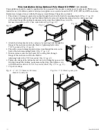
Pole Mount: refer to detailed instructions on page 10.
Note: All inlets for conduit fittings should be on the bottom of the enclosure.
5. Mount circuit board in enclosure with hardware.
6. To facilitate wire entry utilize weather tight NEMA rated connectors (supplied), bushings, and cable.
7. Connect Coax from eBridge1SPR/100SPR (60W), eBridge100RM, eBridge400RM, eBridge800RM or
eBridge1600RM (60W) receiver to connector marked [COAX INPUT] (Fig. 5, pg. 3).
Connect Cat5 from Pace1PRD (60W), Pace1PRM, Pace4PRM, Pace8PRM Pace16PRM (30W)
receiver, NetWay1D or Midspan or Endspan (30W) connector marked [CAT INPUT] (Fig. 5, pg. 4)
8. Select input power SW3 on switch marked [60W CAT, 30W CAT or 60W COAX] (refer to
Input Power Options and Switch Settings on pg. 1, Fig. 1, pg. 2).
9. Connect structured cable from one (1) 60W camera/device to RJ45 jack marked [Port 1] or
connect two (2) individual structured cables from two (2) 30W cameras/devices to RJ45
jacks marked [Port 1], [Port 2] (Fig. 5, pg. 3).
Note: The eBridge is designed to accommodate Megapixel, HD720, HD1080 and VGA (SD) cameras. It is important
to note that some high resolution and high frame rate cameras may demand faster headend processing ability, such as a
PC graphics card to present a quality image. If the headend processing equipment is insufficient in speed, the image may
show pixelation and latency. It is advisable to pretest system if unsure. Alternatively, frame rate and resolution may be
reduced to accommodate system equipment.
Reset Factory Settings:
1. Power the unit down by removing coax or Cat5e wire from input.
2. Depress and hold down Reset button (Fig. 2) while reconnecting coax or Cat5e wire to input.
3. The Heartbeat LED to the left of the Reset button (Fig. 2) will flash twice indicating unit is
reset to factory default.
Fig. 3 - Bottom of enclosure
0.875”
22.22mm
4.25”
107.95mm
2.4375”
61.91mm
1.125”
28.575mm
1.125”
28.575mm
1.25”
31.75mm
Suggested area
for Inlets
SW3
60W CAT
30W CAT
or
60W COAX
Fig. 1
Fig. 2
LED1
SW1


