Alpha Evoke 28 Installation And Servicing Instructions Download Page 10

10

4  GENERAL BOILER INFORMATION

Alpha Evoke 28 and 33 - General Boiler Information

4.1  GAS SUPPLY

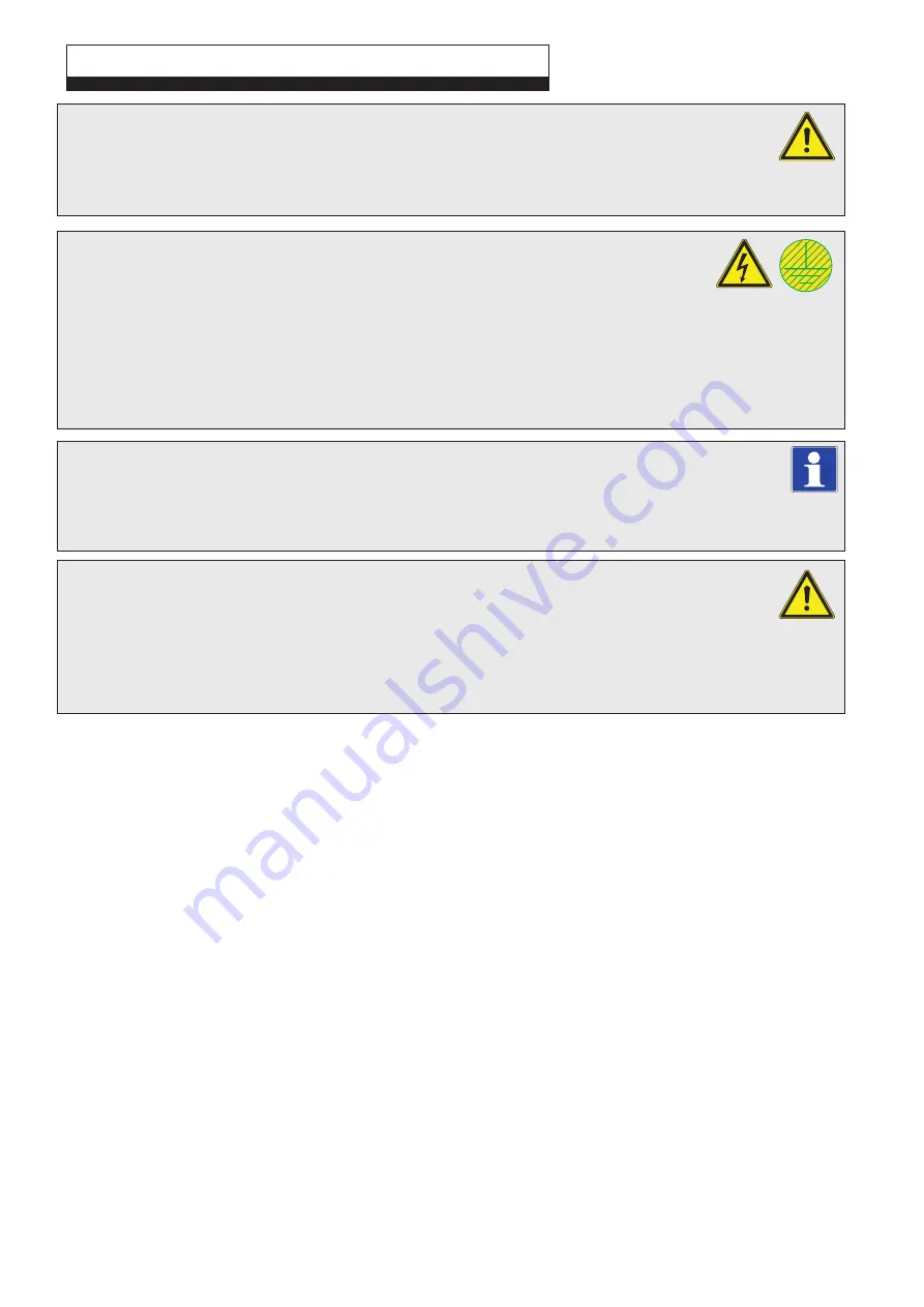
The meter and supply pipes must be capable of delivering the required quantity of gas in addition to the demand 
from any other appliances connected to the same gas supply.
Refer to Technical performance data in Section 3.1 and 3.2.
The complete installation, including the meter, must be tested for gas tightness and purged as described in BS 6891.

4.2  ELECTRICAL SUPPLY

The boiler requires a 230/240 V ~ 50 Hz mains supply, fused at 3 A

The boiler must be earthed.

There must only be one common isolator, providing complete electrical isolation, for the boiler and any external controls.
This boiler has been fitted with a supply cable, however, if it is necessary to fit a cable use PVC insulated cable not less than 
0.75 mm² (24 x 0.2 mm) to BS 6500 Table 16. The boiler should be connected to a fused three pin plug and unswitched shuttered 
socket outlet (both complying with BS 1363), or a fused double pole switch with a contact separation of at least 3 mm in both poles.
Wiring external to the boiler must be in accordance with the current IEE Wiring Regulations (BS 7671).

Note: 

If a room thermostat is fitted, it must be suitable for 230/240 V switching.

4.3  AIR SUPPLY

The boiler does not require any air vents for cooling in the room in which it is installed or when installed in a 
cupboard or compartment. The minimum clearances for servicing must always be maintained.

Note: 

A cupboard or compartment used to enclose the boiler must be designed and constructed specifically for the purpose, 

i.e. comply with the Building Regulations.

4.4  FLUE SYSTEM - Figs. 4.1, 4.2

The flue system must be installed in accordance with BS 5440:1.

When using a horizontal flue kit ensure that the flue outer duct is installed horizontally (please note that the flue 
inner duct already has a pre-determined slope towards the boiler for condensate to run back towards the boiler).
When additional flue extensions are used, ensure the flue slopes downwards towards the boiler by a minimum of 25 - 30 mm 
per metre of flue.
Horizontal and vertical flue assemblies should be supported every metre with access provided to the joints.

Additional flue components are available as follows:-
CD EasyFlue 500 mm telescopic terminal - Part No. 6.12000510.
CD EasyFlue 1000 mm telescopic terminal - Part No. 6.12001010.
CD 750 mm flue extension - Part No. 6.2000750.
CD 1000 mm flue extension - Part No. 6.2001050.
CD 100 mm flue support brackets (pack of 5) - Part No. 6.1000355.
CD 90° bend - Part No. 6.2000590.
CD 45° bend - Part No. 6.2000545.
CD Vertical flue terminal kit - Part No. 6.2000520. Refer to the separate installation instructions supplied with the kit.
Flue support brackets - Part No. 6.1000355.
Terminal guard - Part No. 6.2000570.
Additional flue accessories and plume management are also available.

Note: 1. 

If  an extra 90° bend is used, this reduces the maximum flue length by 1.3 m. Each 45° bend used reduces the 
maximum flue length by 0.9 m.


2. 

Under no circumstances must the flue length (including allowances for extra bends) exceed 12 metres horizontally 
and only 14 metres vertically.


3. 

Failure to use Alpha flue components with the boiler will invalidate the boilers CE approval, guarantee and may be 
unsafe.

Summary of Contents for Evoke 28

Page 1: ...871 8764 website www alpha innovation co uk Set for use with Natural Gas Leave these instructions with the User These instructions have been carefully prepared but we reserve the right to alter the s...

Page 2: ...eport product faults and concerns to the manufacturer in a timely manner Customer Service Show the customer any identity card that is relevant to the work being carried out prior to commencement or on...

Page 3: ...tion for Water Heating Appliances BS 6798 2009 Specification for Installation gas fired boilers up to 70 kW BS 6891 2005 A2 2008 Installation of low pressure Gas Pipework IGEM UP 2 Installation of pip...

Page 4: ...erminal connection point READ AND UNDERSTAND THE INSTRUCTIONS Read and understand the appliance s instructions before performing any operation carefully following the indications provided RECOVERABLE...

Page 5: ...perature Set point C Gas burner injector diameter mm DHW flow rate at 35 C rise l min DHW flow rate at 30 C rise EN13203 1 l min Dry NOx weight net calorific value mg kWh Dry NOx ppm NOx Class Factory...

Page 6: ...eed range in the boiler parameter menu Fixed The pump runs at a constant speed by setting the same minimum and maximum speeds See parameters A1 and A2 in Section 6 13 Constant The pump speed is contro...

Page 7: ...closed dotted area A B Head available with by pass closed B Head available with by pass open C D Power consumed by the pump with by pass open dotted area D Power consumed by the pump with by pass clo...

Page 8: ...Appliance Must Be Earthed Optional integral single channel controls are available if required Note Only use the Alpha single channel controls Do not fit any two channel controls 3 6 ELECTRICAL CONNECT...

Page 9: ...Flue test point pressure point 18 Air test point pressure point 19 Burner 20 Primary return sensor 21 Fan 22 Automatic air vent 23 Boiler pump 24 Primary pressure switch 25 DHW heat exchanger 26 Diver...

Page 10: ...must be designed and constructed specifically for the purpose i e comply with the Building Regulations 4 4 FLUE SYSTEM Figs 4 1 4 2 The flue system must be installed in accordance with BS 5440 1 When...

Page 11: ...al Boiler Information L A B 90 bend 1 3 metre L A 2 x 45 bends 1 8 metre Fig 4 2 VERTICAL FLUE OPTIONS Hmax 14 m Hmax 12 2 m 14 m 1 8 m 12 m B A A B A HORIZONTAL FLUE OPTIONS Lmax 12 metres Not less t...

Page 12: ...sition must allow the free passage of air across it at all times 8 The flue terminal must be positioned where products of combustion will freely disperse and not cause a nuisance 9 Where a terminal is...

Page 13: ...ustible material without the use of a special thermal insulation barrier If the boiler is to be fitted in a timber framed building it should be fitted in accordance with the Institute of Gas Engineers...

Page 14: ...d for the system unless separate zone valves have been installed 4 8 FILLING THE CENTRAL HEATING SYSTEM Fig 4 6 The system design pressure cold should be set to 1 0 bar This pressure is equivalent to...

Page 15: ...rom entering and damaging the boiler Once the system condition has been restored an effective magnetic filter and strainer should be fitted permanently to the system as a method of collecting any magn...

Page 16: ...be made to treat the feed water to the hot water circuit of combination boilers to reduce the rate of accumulation of limescale To ensure economic use the pipe runs between the boiler and taps should...

Page 17: ...ting of the flue using the flue sealing collar supplied cut a 130 mm dia flue hole using a 127 mm core drill 5 Drill the fixing holes 10 mm dia to accept the No 10 plugs supplied Using the screws supp...

Page 18: ...a sack truck or other suitable trolley Always grip the boiler firmly and before lifting feel where the weight is concentrated to establish the centre of gravity repositioning yourself as necessary Ap...

Page 19: ...d Note Always ensure that there is a minimum overlap of 25 mm when fully extending the telescopic section 4 Pass the flue assembly through the wall from inside or outside Note Internal fitting If ther...

Page 20: ...by pushing the inside flue sealing collar up to the wall The hole around the flue can be made good using the flue sealing collars supplied or using a suitable sealant cement if required Fig 5 8 Fittin...

Page 21: ...ensure the slope towards the boiler is correct 3 Determine the overall flue length as described in Section 4 6 paragraph 2 to determine the number of Alpha CD 750 or 1000 mm flue extensions required 4...

Page 22: ...securing the terminal and remove the terminal by pulling it from the flue assembly Remove the screw 2 in Fig 5 12 securing the terminal end section and remove the end section from the terminal ii Loc...

Page 23: ...sy Flue Ensure there is a slope of approximately 3 back towards the Easy Flue Fig 5 13 Note The equivalent horizontal flue assembly length the equivalent plume management length PM length must not exc...

Page 24: ...t and correct operation of the boiler Please note that using controls that are not supplied or recommended by Alpha may invalidate the boiler warranty and may not control the boiler correctly Alpha of...

Page 25: ...er to parameter P7 see Section 6 13 to select the correct parameter to allow the boiler to operate with alternative control type 1 External Sensor Weather compensation feature The E Tec Plus boilers h...

Page 26: ...remove the air Vent each radiator in turn starting with the lowest in the system 5 Check the operation of the safety valve see Fig 7 6 by turning the head anti clockwise until it clicks The click is...

Page 27: ...nd the RESET button remains active on the boiler control panel along with the standby button off mode only and the display where the functioning state is shown Note If the boiler is switched off the C...

Page 28: ...for hot water by opening a hot tap etc is sensed by the flow switch the pump starts the fan will run and the burner lights increasing immediately to its maximum output Water in the boiler is then div...

Page 29: ...er will have a higher noise level this is normal 6 7 FINAL COMMISSIONING 1 Allow the heating system to heat up then balance the system to achieve the necessary temperature difference across the heatin...

Page 30: ...electric and gas supplies Replace the injector located on the upper fitting of the gas valve and re seal the connections Fig 7 6 Re instate gas and electric supplies Calibrate the new fan speed for LP...

Page 31: ...with no DHW demand use the DHW down button to set the output to minimum 0 Insert the analyser probe into the flue test point Fig 6 3 and check that the CO2 value is as specified in Section 3 1 otherw...

Page 32: ...ing the CH up and down buttons you can adjust its value To access the programming menu press andholdthe RESET and INFO buttons atthesametimefor5seconds thedisplay will show two flashing dashes next en...

Page 33: ...pump active 7 Alpha Trace heating cable enabled 8 Not used 9 FlowSmart function enabled The boiler pump can function in two ways 0 Intermittent The pump is controlled according to the heating request...

Page 34: ...ater request the boiler will switch to central heating mode if there is a request It is possible to set a time delay in which the boiler waits before changing back to heating mode in order to quickly...

Page 35: ...e analyser manufacturers requirements 3 Competence can be demonstrated by satisfactory completion of the CPA1ACS assessment which covers the use of electronic portable combustion gas analysers in acco...

Page 36: ...system pressure is zero 2 The expansion vessel pressure test point is accessible from on top at the top left side 5 Check that the condensate trap drain pipe is connected and all joints are sound 6 R...

Page 37: ...nels Fig 7 4 8 Remove the screws H securing the side panel I Lift the side panel and pull it forwards unhooking it from the rear panel view A in Fig 7 4 Lower the panel out and away from the top cover...

Page 38: ...ctrodes If they are in good condition remove any oxide deposits using a fine abrasive paper If it is necessary to replace the electrode assembly ensure a new gasket is used 3 Check that the fan is cle...

Page 39: ...te trap 9 DHW flow switch 10 Gas injector 11 Gas valve 12 DHW heat exchanger 13 Boiler drain point 14 DHW temperature sensor 15 Test points air A flue F 16 Flue temperature sensor 17 Four fixing nuts...

Page 40: ...e pipe 6 Re fit the ignition lead to the electrode 7 Check all the connections are sound and re commission Sections 6 3 and 6 8 8 Raise the control panel and clip into place 9 Check that the insulatio...

Page 41: ...ponents and care must be taken when removing them 8 3 IGNITION AND SENSING ELECTRODES Fig 7 6 Gain access as described in Section 8 1 1 Pull off the ignition lead from the electrode 2 Remove the cap s...

Page 42: ...he PCB cover ensure no wires are trapped and all wiring is secured Secure cover with three screws do not over tighten 6 Set the correct parameters for the correct boiler model as described in Section...

Page 43: ...ve 6 Fit the new switch and re assemble in reverse order 7 Visually inspect for leakage after reconnecting the mains cold water supply 8 13 PRIMARY HEAT EXCHANGER Fig 7 6 Gain access and drain the boi...

Page 44: ...Refill and pressurise the system Refer to Commissioning Section 6 1 8 17 PUMP HEAD Fig 7 6 Gain access and drain the boiler heating circuit as described in Sections 8 1 and 8 2 1 Disconnect the two w...

Page 45: ...th the locating lug at the top and push firmly into place Using the supplied tool and a suitable spanner turn the cartridge clockwise until the retaining lugs are locked into position 5 Pull the diver...

Page 46: ...s M1 Y Br G Y Bk PWM GND FEED Bl Br L N B2 S4 G GY GY G Y1 Y R Br Br Bk Bl M E3 M30 Br Y Bk Br R Bl 6 1 9 1 W P Or R W Or P R W W P P Fuse 3 15 AF Vcc HS UB GND Vcc M20 Bl W R Bk Br Br R Bl W Bk 1 5 X...

Page 47: ...sel pressure 1 bar Leak in system Expansion relief valve operated Primary pressure switch Check sensor wiring and connections Check sensor resistance Check the settings of the A family parameters Chec...

Page 48: ...ir flow blocked Flue restriction Flue sensor fault Pump fault Batteries require replacing Check the pump operation it may be necessary to free the pump shaft refer to Section 3 4 Check the pump wiring...

Page 49: ...de for 24 hrs to allow the display to be read To permanently reset the error Sr E97 1 Enter the parameter menu using the password 69 See Section 6 13 2 Parameter P6 will show 0 3 Set P6 to any value a...

Page 50: ...sate connecting pipe Expansion vessel Fan Flue sampling point cap Complete boiler seal kit Hydraulic circuit seal kit Complete heat exchanger seal kit Gas pipe to fan manifold Gas pipe O ring Clip Flo...

Page 51: ...Low temperature means for condensing boilers 30 C for low temperature boilers 37 C and for other heaters 50 C return temperature Model s Evoke 33 Condensing boiler YES Low temperature boiler NO B1 bo...

Page 52: ...COMPLIANCE WITH REGULATION 811 2013 Parameter value Yearly energy consumption for the hea ting function QHE 1 5 GJ Yearly electricity consumption for the domestic hot water function AEC 29 kWh Yearly...

Page 53: ...uenced by further factors such as heat loss in the distribution system and the dimensioning of the products in relation to building size and characteristics Seasonal space heating energy efficiency of...

Page 54: ...II III I Auxiliary electricity 3 G F E D C B A A A A 27 27 27 28 27 27 27 28 30 30 30 32 33 34 35 36 36 37 38 40 39 50 55 60 65 75 80 85 100 115 123 131 130 150 160 170 163 188 200 213 M L XL XXL 3 2...

Page 55: ...ficiency once installed in a building as the efficiency is influenced by further factors such as heat loss in the distribution system and the dimensioning of the products in relation to building size...

Page 56: ...36 36 37 38 40 39 50 55 60 65 75 80 85 100 115 123 131 130 150 160 170 163 188 200 213 M L XL XXL 3 2 3 2 The energy efficiency of the package of products provided for in this fiche may not correspon...

Page 57: ...57 Alpha Evoke 28 and 33 Page intentionally Blank...

Page 58: ...re and record Gas rate m hr OR ft hr Burner operating pressure if applicable mbar OR Gas inlet pressure mbar Central heating fow temperature C Central heating return temperature C COMBINATION BOILERS...

Page 59: ...gister No Record At max rate CO ppm AND CO At min rate Where Possible CO ppm AND CO Comments Signature SERVICE 04 Date Engineer name Company name Telephone No Gas safe register No Record At max rate C...

Page 60: ...the National Gas Emergency Service immediately on 0800 111 999 8 ELECTRICAL SUPPLY The boiler requires a 230 240 V 50 Hz supply fused at 3 A To connect a plug The colour of the wires in the mains lea...

Page 61: ...em for external condensate drainage pipework incorporating an external frost thermostat should be considered 7 GAS SAFETY REGULATIONS Current Gas Safety Installation and Use Regulations It is the law...

Page 62: ...not the desired room temperature The time and temperature will still be maintained according to the setting of the room thermostat 3 HEATING AND HOT WATER TEMPERATURE Fig 2 External weather compensat...

Page 63: ...mer or Winter settings by pressing the Mode button item 1 in Fig 1 Summer setting The boiler will only provide hot water when a tap is turned on and the central heating will not activate even if reque...

Page 64: ...enoaks Kent TN15 7RS For Technical help or for Service call ALPHA HELPLINE Tel 0344 871 8764 website www alpha innovation co uk Set for use with Natural Gas Leave these instructions with the User Thes...

Reviews: