26
Y4
1
2
3
4
1
2
3
1 2 3 4 5 6
Y3
Y2
12 11 10 9 8 7 6 5 4 3 2 1
0 1
2
3
4
5
6
7
8
9
9
8
10 11 12 13 14
2
1
3
4
5
6
7
Jp2
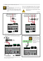
Stemp ACC.
S
temp.
A
C
C
(-)
G
N
D
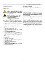
Instructions for the installer
NOTE:
Th
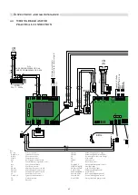
e boiler is provided with set-up to manage one direct
flo
w and one storage tank.
If Stemp. ACC is connected automatically, the DHW
service is enabled, which will be managed as a priority
compared to direct
flo
w through the pumps shown
below.
If the storage tank temper-
ature sensor is connected,
the DHW is automatically
activated when the boiler
is powered.
The code (803) Srv (see
BCM parameters) changes
from 19 to 27.
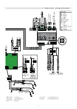
If other services (storage tanks, mixed zones, solar, etc.) are requested,
it is necessary to purchase SHC multifunction modules to connect to
the local bus for total temperature control management via HSCP.
Th
e BCM relay contacts support pumps with max
absorption of 4 A.
(*) Optional
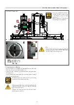
P. Coll - Pump Manifold (*) (Primary ring)
P. CH - Heating circuit pump (central heating circuit)
P. Car DHW - Storage tank load pump
Stemp. ACC. Storage Tank Temperature Sensor (*)
- Connect the cables as indicated (Y4 1-2).
- Connect the temperature sensor cables as indicated (Y2 4-8).
Connection Mod. P. Central Heating Modulating Pump
(Optional)
Connect the modulation control cables as indicated (
Y2
5
-
6
).
External power supply 230 V-50 Hz.
Summary of Contents for ARES Pro 150
Page 2: ......


