9
S
R
G
*53
18
54
27
60
56
57
14
58
32
S.cond
59
3
19
61
62
28
10-11
63
64
M
55
5
33
S.cond
59
S
32
58
14
57
56
R
27
M
18
60
19
3
61
62
G
28
10-11
53
63
64
54
55
5
33
Technical features and dimensions
2
TECHNICAL FEATURES
AND DIMENSIONS
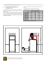
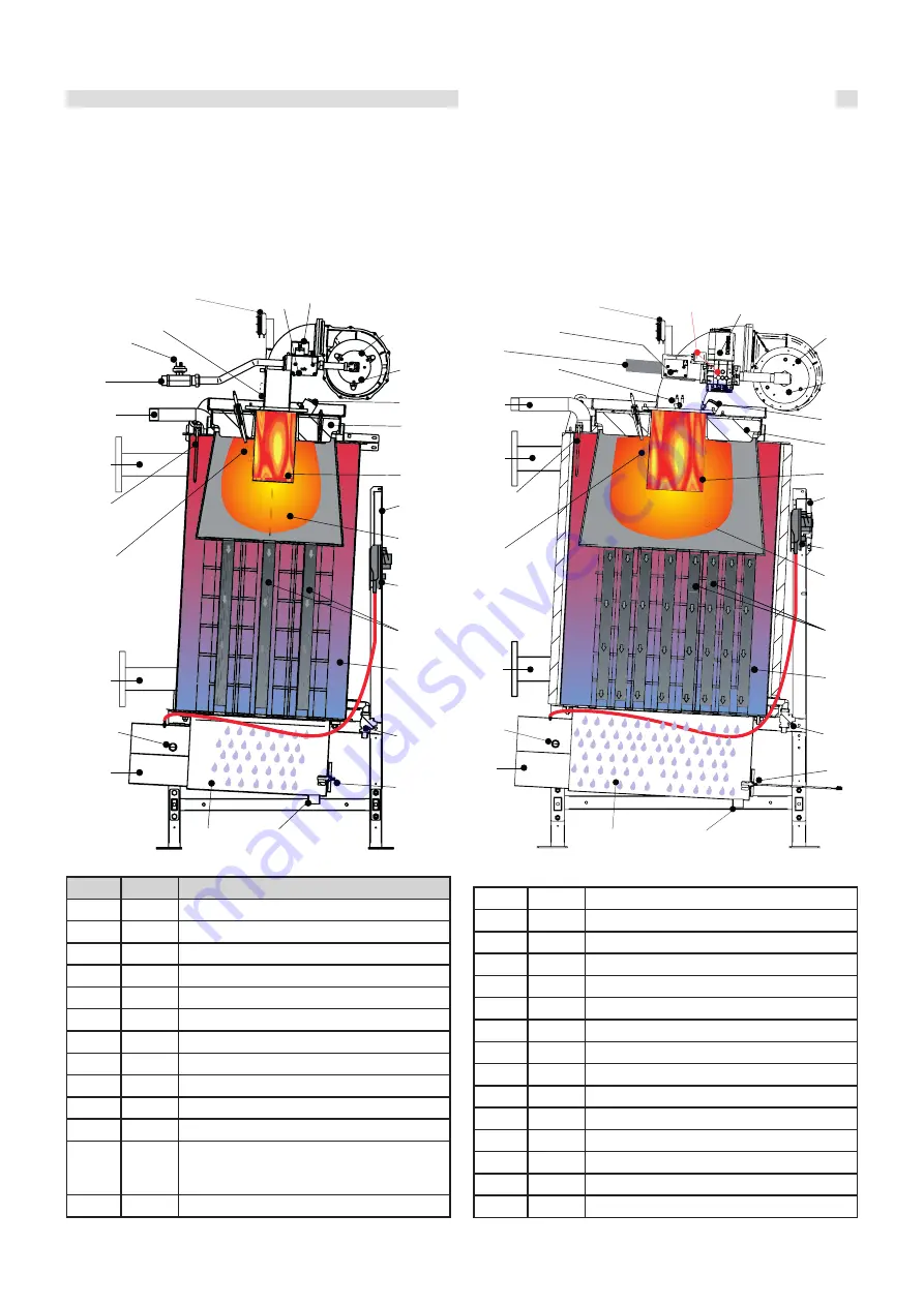
2.1 INTERNAL VIEW WITH INDICATIONS
OF MAIN COMPONENTS
Key:
N°
S.E.
Description
3
VG
Gas valve
5
Burner
10
TL
Probe Limi
t Th
ermostat
11
SR
Central heating sensor
14
Boiler draining valve
18
VM
Fan
19
PF
Flue pressure switch
27
E. RIL. Detection electrode
28
E. ACC. Ignition electrode
32
Flue inspection point
33
Control panel
53
PGmin
PGmax
Gas pressure switch (min. *ARES PRO 150)
(min. ARES PRO 230 - 300)
(min. / max ARES PRO 348 ÷ 600)
54
Glass inspection hole
55
Door insulation
56
Stainless steel vertical smoke pipe with aluminium internal.
57
Technical water tank
58
SL
Level sensor
59
Condensate collection pan
60
Combustion chamber
61
Mixer Aria/gas
62
T.ACC Igniters
63
PFmin M
in. fl
ue pressure switch
64
Air ven
t fi
tting
G
Gas inlet
M
Central heating syst
em flo
w
R
Central heating system return
S.cond
Condensate drain DN 32
S.E.
= WIRING DIAGRAM KEY
ARES PRO 150
ARES PRO 230 - 300 - 400 - 500 - 600
Summary of Contents for ARES Pro 150
Page 2: ......


