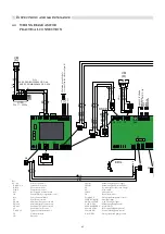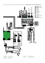
39
Inspections and maintenance
777
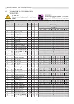
AFC
APS Control
0
2
0
805
LV
Mains Voltage
V
100
240
230
2590
Burner Power
kW
10
1000
150
214
280
348
380
450
550
( ) Values for LPG
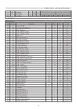
BCM Parameters
Code
Symbol
Description
Unit
Min.
Max.
Sys. Fab.
803
Srv
Services Enabled
16
27
19
483
rP
Gen: Temp. M
ax Diff
erential
°K
0.0
50.0
0
34
HY
Burner Hysteresis
°K
5.0
20.0
5.0
31
HL
CH#1: Minimum Setpoint
°C
20.0
40.0
35.0
39
HH
CH#1: Maximum Setpoint
°C
45.0
85.0
80.0
799
AC
Input 0/10V
0
3
1
376
DI1
Programmable Input #1
0
2
0
322
Po
Pump Post-circulation
min.
1
10
5
341
PL
Pump Minimum Control
V
0
10
3
313
Pr
Pump Maximum Control
V
0
10
10
792
CHP
CH: Max Modulation
%
0
100
100
611
POT
Gen: Err. Max. Parallel
°K
0
30
5
612
POL
Gen: Mod. Max. Parallel
%
0
100
0
650
dL
DHW: Minimum Setpoint
°C
25.0
45.0
35.0
385
dH
DHW: Maximum Setpoint
50.0
65.0
65.0
360
dt
Storage tank adjustment
0
15
0
656
drT
DHW: Temp. Reques
t Diff
erential
°K
-20
20
4
657
drH
DHW: Request Temp. Hysteresis
°K
1
20
8
310
DpT
DHW Pump: Postcirc.
sec.
5
600
60
660
dbT
DHW: Temp. Boiler Maximum
°C
50.0
85.0
75.0
48
ChSet
CH#1: Setpoint
°C
20.0
85.0
85.0
64
ChPO1
CH#1: Parallel Supply
0
1
0
346
FL
Minimum Modulation
%
0
100.0
25.0
600
mB
Burners: Min. Inserted
1
8
1
616
BSt
Gen: Insertion Time
sec.
30
900
120
613
BRt
Gen: Removal Time
sec.
30
900
120
336
HS
Temperature Gradient
°C/min
1
30
5
353
HP
CH PID: Proportional
°K
0
50
25
354
HI
CH PID: Integrative
°K
0
50
12
478
Hd
CH PID: Derivative
°K
0
50
0
816
MI
ModBus Address
1
127
1
817
MT
Timeout Modbus
sec.
0
240
30
896
TU
°Fahrenheit
0
1
0
309
St
Application Code
0
1
1
368
VA1
Programmable Relay #1
0
1
0
369
VA2
Programmable Relay #2
0
1
1
771
PS
Water Pressure Sensor
0
1
0
768
LG
Min. Gas Pressure Sens.
0
1
1
793
COC
Chimney Obstruction Sens.
0
2
1
622
FS
Minimum Flow Sensor
0
1
3
Summary of Contents for ARES Pro 150
Page 2: ......

