


24
Subject to change without notice | 83050400fUK – Translation into English of the original German operating manual | ait-deutschland GmbH
the heating fill and additional water, the heating water
should also be appropriately conditioned. This is the
only way to comply with the VDI 2035 requirements and
the recommendations and installation instructions of the
heat pump manufacturer.
Part 2 of VDI 2035 also points out the reduction in total
salt content (conductivity). The risk of corrosion is far
lower if deionised water is used than is the case if the
system is operated with salty, i.e. softened water.
Even if the water has been softened beforehand, it
contains dissolved, corrosion-promoting salts, which act
as electrolytes due to the use of different materials in
the heating system and therefore accelerate corrosion
processes. This can ultimately result in pitting.
Contamination and deposits in the heating circuit can
cause malfunctions
ON THE SAFE SIDE WITH LOW-SALT OPERATION
The problems listed above do not occur at all with
low-salt operation, as neither corrosive salts such as
sulphates, chlorides and nitrates nor alkalising sodium
hydrogen carbonate are in the heating water. The
corrosive properties of deionised water are very low
and in addition, fur cannot form in the boiler. This is the
ideal approach for closed heating circuits, in particular,
because low oxygen input into the heating circuit can
also be tolerated.
In general, when the system is filled with deionised
water, the pH value sets itself within the ideal range due
to “self-alkalinisation”. If necessary, a pH value of 8.2
can be very easily alkalised by adding chemicals. In this
way, optimum protection of the entire heating system is
achieved.
MONITORING
Analytical recording and monitoring of the relevant
water values and the added active conditioning
substances is of decisive importance. Therefore, they
should be monitored regularly using appropriate water
test equipment.
RINSE, FILL AND BLEED THE HEATING CIRCUIT AND
HOT WATER BUFFER TANK
To bleed the hot water tank, the heating circuit and hot
water circuit must be rinsed simultaneously.
LWC 60 – LWC 100
:
If unit is closed, open bottom front panel…
“Transport with a hand truck”
Loosen quick-release screws for the lower front
panel (= control side), remove lower front panel and
set aside…
Rinse and fill unit via the filling and emptying valve…
ATTENTION
Do not exceed a pressure of 2.5 bar when rins-
ing the unit. The drain line of the heating circuit
safety valve must be closed before rinsing and
filling.
NOTICE.
Rinse heat pump and heating circuit for about 5
minutes.
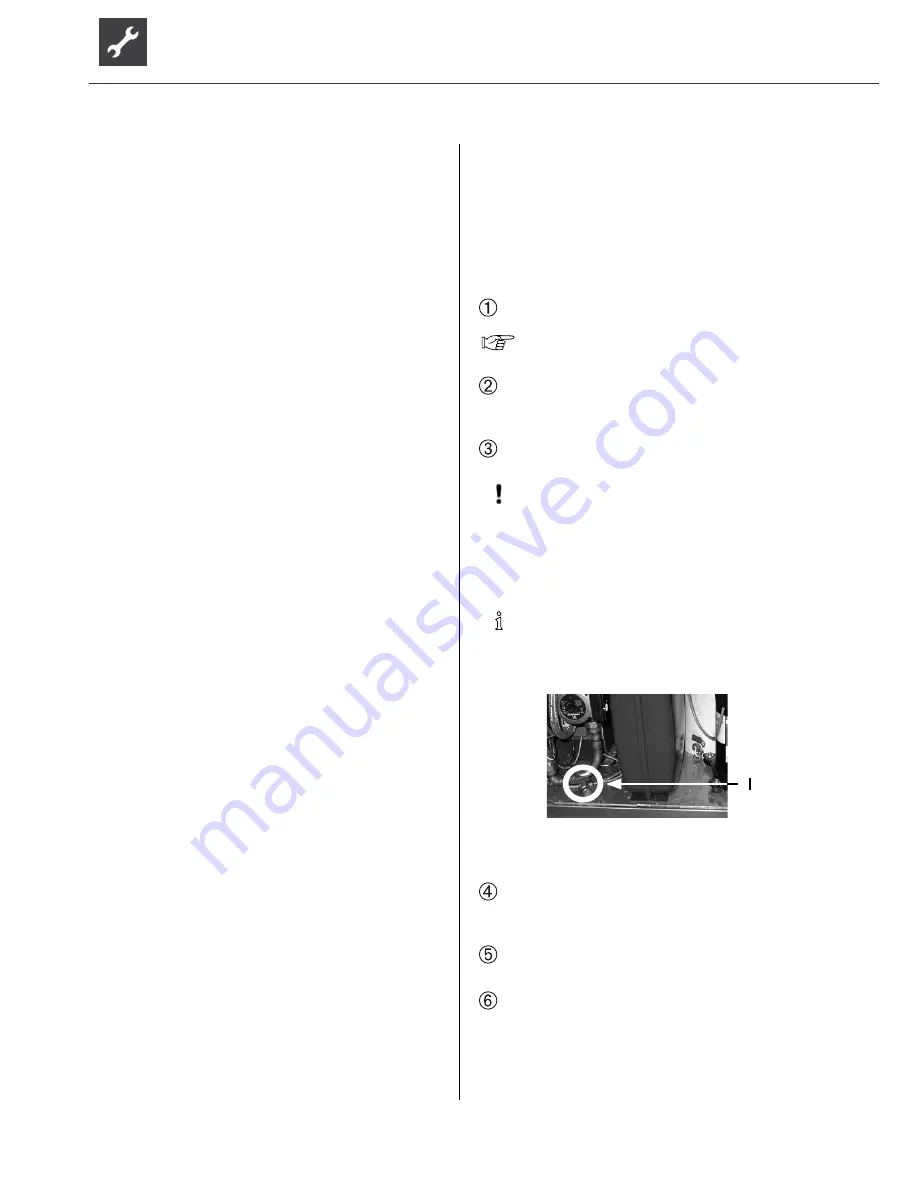
LWC 100
1 filling and emptying valve
Remove the motor of the 3-way valve. To do so,
remove the U-bolt on the motor base and carefully
pull the motor to the side…
Turn spindle 180° and rinse hot water circuit ca. 1
minute…
Turn spindle 180° back to starting position (rounded
side of spindle points to B)…


