Installation
16
900-0184-01-00 Rev A
Optional Connections
RSI
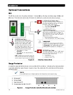
The RSI has several sets of auxiliary terminals. Terminal
J6
has a factory-installed jumper.
J3
,
J4
, and
J5
do not. The terminals can be wired to alarms or switches to send or receive status messages.
Figure 5
Interface Connections
Surge Protector
An optional surge protection device can be installed in the combiner. A knockout has been provided
to accommodate this type of device. Figure 6
shows the underside of the combiner and the location
of the knockout.
NOTE:
Any installed devices must be liquid-tight to sustain the combiner’s environmental rating.
Figure 6
Surge Protector and other Knockout Locations
J5 AUX AFCI Status Output
Dry contacts which report AFCI status. The
J5
contacts
can activate a local alarm or send status messages to
the Internet or other OutBack devices.
Open: Normal
Closed: Arc Fault Event
30 Vdc or 15 Vac @ < 2 A
J3: AUX RSI Command/Status Output
Dry contacts which report RSI status. The
J3
contacts
can activate a local alarm or send status messages to
the Internet or other OutBack devices.
Open: Rapid Shutdown (
SOLAR OFF
)
Closed: Normal (
SOLAR ON
)
30 Vdc or 15 Vac @ < 2 A
J4: AUX RSI Safe Status Input
Switch contacts in parallel with the Breaker RSI Safe and
PV RSI Safe wires from BKR-CTRL-DC. (See page 15.)
These connections close a 24 Vdc “Safe” status circuit.
An external switch or relay can send a “Safe” signal to
J4
from another location.
Open (all connections): Not “Safe”
Closed (any connection): “Safe” (Rapid Shutdown)
IMPORTANT:
If BKR-CTRL-DC or other devices are not installed, a
jumper must be installed on
J4
. With no connections,
the
SOLAR OFF
(“safe”) indicator will not light even if
the Rapid Shutdown switch is OFF. (See page 17.)
J6 AUX RSI External Input
Switch contacts in series with the main
Rapid Shutdown switch. These connections
(normally closed) control a 24 Vdc Rapid
Shutdown circuit. Opening any contacts
constitutes a Rapid Shutdown command.
An external switch or relay can serve as
another rapid shutdown device if connected
to the
J6
contacts from another location.
Closed (J6 and R.S.): Normal
(
SOLAR ON
)
Open (either J6 or R.S.): Rapid Shutdown
(
SOLAR OFF
)
NOTE
: The
J6
jumper must remain in place if an
external switch is not connected. Leaving these
contacts open will cause a continuous shutdown.
A.
PV Conduit (2”)
B.
PV Cable Glands
C.
Surge Protector (½”)
D.
Communications Conduits (½” and ¾”)
A
B
C
D

