900-0184-01-00 Rev A
13
Installation
This section assumes the use of the combiner, the RSI, the BKR-CTRL-DC and the RTB. The combiner
box is a required part of all ICS Plus systems. All examples in OutBack literature show one or more
combiners in use, including the
ICS Plus Quick Start Guide
.
The RSI is required for all ICS Plus systems utilizing the PVRSS function. For examples of systems which
may not require the use of the RSI, see page 17. Also see page 17 for examples of systems which may
not require the use of the BKR-CTRL-DC or the RTB.
Mounting Information
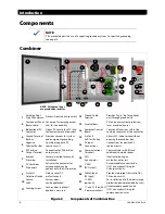
The ICS Plus combiner box accommodates multiple mounting types.
It can be mounted horizontally, vertically, or at any intermediate angle.
It has slotted mounting feet which allow a variety of positions.
It is capable of being mounted directly under the PV array if necessary.
It must be mounted at least 36” (91.4 cm) above the ground.
The combiner box has a latch which should be padlocked to limit internal access.
The main disconnect can also be padlocked in the OFF position for safety.
NOTE:
If the box is not padlocked, the securing screw must be used to secure the door.
See Figure 2 on page 8.
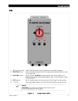
The RSI has mounting brackets at the top and bottom.
It should be installed near the service meter.
It must be mounted vertically and must be at least 36” (91.4 cm) above the ground.
The Rapid Shutdown switch can be padlocked in the OFF position for safety.
NOTE:
If the structure where the RSI is installed is also equipped with utility service, the structure must
have a permanent sign or plaque reading “PHOTOVOLTAIC [or PV] SYSTEM EQUIPPED WITH
RAPID SHUTDOWN”. This plaque must be reflective, with all letters capitalized and having a
minimum height of
⅜
” (9.5 mm) in white on red background.
The BKR-CTRL-DC is intended to be installed in the load center in most cases.
When using the FLEXware 500 or 1000, it is installed in one slot in the DC enclosure.
When using the FLEXware 250, it is not installed inside the enclosure. It is installed externally using the
included bracket. It connects alongside the FLEXnet DC Battery Monitor.
When using the GSLC, it is installed in one circuit breaker slot on the DC rail.
If necessary, the slotted holes on the included bracket allow it to be installed in various external locations on
the GSLC or the Radian inverter.
The RTB is intended to be installed in the load center.
Each RTB takes the place of a PV input circuit breaker.
Note that each RTB assembly requires an additional circuit breaker slot. For example, PNL-75D-DC-RT
requires three slots. PNL-75Q-DC-RT requires five slots.

