background image

Functions 


12 

900-0184-01-00 Rev A 

Arc Fault Self-Test 

The arc fault function can be manually tested.  The arc fault self-test mimics the conditions of an arc fault.  
The combiner and RSI give the same indications as described on page 11.   

To perform the arc fault self-test: 

1.


Ensure the system is functioning and all indicators are normal. 

2.


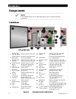
Push the arc fault self-test button as shown in Figure 2 on page 8. 

3.


Listen for an audible click as the contactor opens. 

4.


Check the

 AFCI Annunciator

 on the combiner.  It should be illuminated. 

5.


Optional (if installed):  Check the 

AFCI

 indicator on the RSI.  It should be illuminated. 

Reset the system by the same method as described on page 11.


Rapid Shutdown 

The rapid shutdown requirement is intended for firefighters or first responders.  In an emergency,  
a responder may need to set the PV system in a “safe” (de-energized) state according to NEC 690.12.   

For this reason, the RSI is required to be mounted close to the main utility meter.  The RSI must be 
easily visible. 

The RSI includes a Rapid Shutdown switch that initiates a disconnection of all elements of the PV 
system.  Opening this switch sends a signal to all combiners to open the main contactor on each.   

Opening this switch also sends a signal to all relay-trip breakers, ordering them to open.   According to 
NEC 690.12, the rapid shutdown must reduce the DC circuit to less than 30 Vdc and 240 VA within ten 
seconds of initiation.  Because many charge controllers have capacitors which may not discharge 
quickly enough, the RTB function removes the controller from the circuit to make it safe. 

Rapid Shutdown Self-Test 

The rapid shutdown should be tested every six months.  This test should be performed as described in 
the Verification section. 

Verification 

Turning the Rapid Shutdown switch to the right (clockwise) puts it in the OFF position.  The  

SOLAR OFF

 LED indicator will illuminate upon successful shutdown.  If this does not occur, see the 

Troubleshooting section on page 19. 


PV Combiner Disconnect


Each combiner has a PV Combiner Disconnect switch which is used to turn off a particular array.  This 
is used if the array or circuit needs to be serviced.  The switch can be padlocked in the OFF position as 
a “lockout/tagout” procedure to prevent a shock hazard. 


Summary of Contents for OutBack Power FLEXware Integrated Combiner Solution Plus

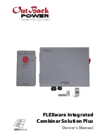
Page 1: ...FLEXware Integrated Combiner Solution Plus Owner s Manual ...

Page 2: ...8 4363 Technical Support 1 360 435 6019 Fax 49 9122 79889 0 49 9122 79889 21 Fax Email Support outbackpower com Website http www outbackpower com Disclaimer UNLESS SPECIFICALLY AGREED TO IN WRITING OUTBACK POWER TECHNOLOGIES a MAKES NO WARRANTY AS TO THE ACCURACY SUFFICIENCY OR SUITABILITY OF ANY TECHNICAL OR OTHER INFORMATION PROVIDED IN ITS MANUALS OR OTHER DOCUMENTATION b ASSUMES NO RESPONSIBIL...

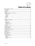
Page 3: ...nterruption 11 Detection 11 Reset 11 Arc Fault Self Test 12 Rapid Shutdown 12 Rapid Shutdown Self Test 12 Verification 12 PV Combiner Disconnect 12 Installation 13 Mounting Information 13 Connection Information 14 Other Applications 17 Alternative System Requirements 17 Positive Ground 18 Troubleshooting 19 LED Indicators 19 Basic Troubleshooting 19 Specifications 21 Device Specifications 21 Regul...

Page 4: ...ranty NOTE This type of notation indicates that the information provided is important to understanding the operation and limits of the equipment Failure to follow the recommendations in such a notation could result in improper or failed operation MORE INFORMATION When this symbol appears next to text it means that more information is available in other manuals relating to the subject The most comm...

Page 5: ...s NEC 690 15 DC combiner disconnect opens all ungrounded circuit conductors from all energy sources Product Overview Features First end to end solution listed to UL1741 with PV rapid shutdown systems PVRSS Arc fault circuit interrupter AFCI listed to UL1699B with local and remote indication Type 3R enclosures rated for indoor or outdoor installation Flexible design install the combiner box vertica...

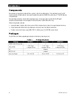
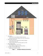
Page 6: ... Rapid Shutdown Initiator RSI which works with the combiner box to induce the rapid shutdown function Relay Trip Breaker RTB which physically opens the circuits near the charge controller s Breaker control and power supply BRK CTRL DC which powers the RSI RTB and combiner Packages The ICS Plus has three prepackaged solutions for battery based systems Table 1 Packaged Systems Package ICSPLUS 1 ICSP...

Page 7: ...sconnect to de energize PV circuits within 10 feet of the array Rapid Shutdown Initiator RSI Contains control circuit for PVRSS contactors and relay trip breakers Includes PVRSS disconnect switch Includes LED indicators for PV connection disconnection or arc fault Relay Trip Breaker RTB Removes charge controller s from PV circuit Can be integrated into OutBack GSLC or FLEXware enclosures Circuit B...

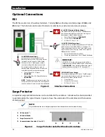
Page 8: ...ive PV source circuits 16 PV Input Connections Connections for positive PV source circuits 6 PV Positive Output Terminal Connection for PV positive output circuit 17 Communications Terminals Communicates with RSI and additional combiner boxes 7 Internal Prewiring Factory installed for ease of installation 18 AFCI Annunciator Illuminates during an arc fault event or test 8 PV Combiner Disconnect Ac...

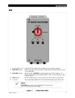
Page 9: ...dicator Red LED indicator SOLAR OFF must be illuminated to confirm PV shutdown This indicator tells responders that the Rapid Shutdown switch is in the OFF position to create a safe condition 4 AFCI indicator Red LED indicator illuminates when receiving an arc fault signal from the combiner 5 3 EKO These accommodate conduit and a UL 514 compliant fitting for communication wires NOTE SOLAR ON does ...

Page 10: ...Introduction 10 900 0184 01 00 Rev A This page intentionally left blank ...

Page 11: ...ating that an arc fault has occurred somewhere in the system If multiple combiners are in use the RSI cannot specify which combiner triggered it Only the combiner with the detected arc will open its contactor Any other combiners in the system will continue to operate Relay trip breakers will continue to operate If an arc fault occurs see the Troubleshooting section on page 19 Upon an arc fault eve...

Page 12: ...d Shutdown switch that initiates a disconnection of all elements of the PV system Opening this switch sends a signal to all combiners to open the main contactor on each Opening this switch also sends a signal to all relay trip breakers ordering them to open According to NEC 690 12 the rapid shutdown must reduce the DC circuit to less than 30 Vdc and 240 VA within ten seconds of initiation Because ...

Page 13: ...ets at the top and bottom It should be installed near the service meter It must be mounted vertically and must be at least 36 91 4 cm above the ground The Rapid Shutdown switch can be padlocked in the OFF position for safety NOTE If the structure where the RSI is installed is also equipped with utility service the structure must have a permanent sign or plaque reading PHOTOVOLTAIC or PV SYSTEM EQU...

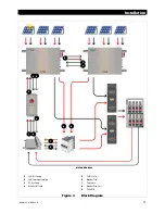
Page 14: ... status information from the combiner s It receives PVRSS status information from the BKR CTRL DC 4 and the combiner s 5 It sends RTB disconnect commands 6 to the BKR CTRL DC Both sets of wires must be connected for correct PVRSS operation BKR CTRL DC The BKR CTRL DC connects to the battery bus in the load center See Figure 4 on page 15 It sends 24 volt power to the RTB 8 and the RSI 1 which in tu...

Page 15: ...1 00 Rev A 15 Figure 4 Block Diagram 1 3 2 via load center 5 7 8 4 2 3 1 24V RSI Supply 5 PV RSI Safe 2 24V Combiner Supply 6 Breaker Trip 3 PV Arc Fault 7 Trip Sense 4 Breaker RSI Safe 8 Breaker Trip Coil 9 PV to RTB 9 5 6 9 ...

Page 16: ...en Rapid Shutdown SOLAR OFF Closed Normal SOLAR ON 30 Vdc or 15 Vac 2 A J4 AUX RSI Safe Status Input Switch contacts in parallel with the Breaker RSI Safe and PV RSI Safe wires from BKR CTRL DC See page 15 These connections close a 24 Vdc Safe status circuit An external switch or relay can send a Safe signal to J4 from another location Open all connections Not Safe Closed any connection Safe Rapid...

Page 17: ...SS NOT required FWPV6 FH600 SDA BKR CTRL DC These battery based applications may require third party equipment which operates in higher voltage ranges 300 to 600 Vdc max array 24 to 48 Vdc battery bank PVRSS required FWPV6 FH600 SDA RSI BKR CTRL DC Third party PVRSE rated for 600Vdc 300 to 600 Vdc max array 24 to 48 Vdc battery bank PVRSS NOT required FWPV6 FH600 SDA BKR CTRL DC These non battery ...

Page 18: ...tions require the disconnection of both the grounded and ungrounded conductors The ICS Plus product depicted here has only a single contactor It will not suffice for these applications IMPORTANT The ICS Plus product depicted here cannot be used in ungrounded systems The relay trip breaker is wired differently from the method in the ICS Plus Quick Start Guide Figure 8 Positive Grounded RTB 1 2 3 1 ...

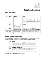
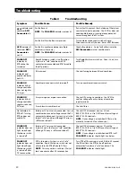
Page 19: ...mbiner AFCI Annunciator red Arc fault condition or deliberate arc fault self test Accompanied by AFCI on RSI Will not be accompanied by AFCI Annunciators in other combiners unless other arc faults are present May be lit at the same time as SOLAR ON Basic Troubleshooting The following table describes known situations which can cause unexpected behavior in the ICS Plus The table also describes all k...

Page 20: ...uced PV input Array wiring error or poor connection Check all PV wiring to combiner Use DVM to confirm voltage of each subarray at combiner input terminals Fuses blown in combiner box Check all fuses No indicators lit RTB off Turning RTB on does not enable PV Battery or DC source is disconnected Loss of combiner box control voltage caused the PV contactor to disconnect System is not in the formal ...

Page 21: ...ble glands 24 to 16 AWG 0 25 to 1 5 mm2 stud 14 to 2 0 AWG 2 5 to 70 mm2 PV input Output 14 to 2 0 AWG 10 32 screw trip sense LED indicators AFCI Annunciator SOLAR ON SOLAR OFF AFCI N A N A Overcurrent Protection 6 600 Vdc DIN rail fuse holders N APNL 3AG Cartridge 3A slow blow 10kA 125VDC N A Voltage Rating 600 Vdc 24 Vdc 3 N A 300 Vdc per pole Total Current maximum 96 Adc N A N A 75 Adc per pole...

Page 22: ... 1 14 2014 CSA C22 2 General Use Power Supplies No 107 1 3 Issue 2001 09 01 Ed 3 R2011 with PV Rapid Shutdown Compliance This product has been tested to comply with the following standards FCC Part 15 Class B FCC Information to the User This equipment has been tested and found to comply with the limits for a Class B digital device when powered by a DC source pursuant to part 15 of the FCC Rules Th...

Page 23: ... PVRSE device CSA Canadian Standards Association establishes Canadian national standards and the Canadian Electrical Code including C22 1 and C22 2 Dry contact A relay contact with no source voltage switches the continuity to be used by an external device DVM Digital Voltmeter EKO Electrical Knockout Grounded Conductor The DC conductor negative or positive which is mechanically bonded to ground in...

Page 24: ... A Masters of the Off Grid First Choice for the New Grid Corporate Headquarters 17825 59th Avenue N E Suite B Arlington WA 98223 USA 1 360 435 6030 European Office Hansastrasse 8 D 91126 Schwabach Germany 49 9122 79889 0 ...

Reviews: