4 - INSTALLATION
4.1 HOISTING OF THE MACHINE
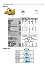
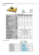
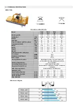
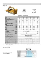
Machine hoisting and transportation must be done only by means of a suitable vehicle that can sustain the weight of
the machine. Hook machine as shown in the following figures and go ahead with the transportation of the machine.
During this operation, the machine must not be hoisted more than 200 mms from the ground.
4.2 PARTIALLY ASSEMBLED MACHINES
Due to their size, these machines are sometimes delivered with loose or disconnected parts (contained in the same
packing). Assembling of these parts must be done very carefully; follow the spare parts diagrams because it is very
important that you respect the screw tightening torque values given by the manufacturer.
4.3 HOOKING-UP TO TRACTOR AND THREE POINT HITCH
The hooking-up procedure to the tractor is a very dangerous and delicate phase. Follow the
instructions throughout the whole operation very carefully. The manufacturer declines liabilities
for any breakages or damages to objects and/or persons caused by operators who do not respect
the enclosed instructions.
To determine the correct tractor/machine relative position, place the tractor away from the machine at a distance
where the P.T.O. joint is extended for 5 -10 cm from maximum closure position.
At this point you can proceed as follows:
1.
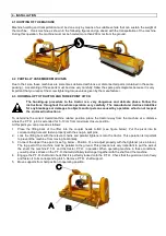
Place the lifting bars of the lifter into the coupler heads A-B-C (see figure below). Put the pivot into its
corresponding hole and fasten properly with the snap-in split pins.
2.
Lock the lifting bars with the relevant chains and parallel tighteners onto the tractor. This operation is important
to prevent the machine from moving horizontally.
3.
Connect the upper three point (see fig. below - Position C) and adjust properly with the tightener (use a brace).
The top part of the machine must be parallel to the ground. This procedure is very important to put the axis of
the shaft, the machine P.T.O. and the tractor P.T.O. in parallel. When operating machine in these conditions,
you will put less stress on the P.T.O. that will definitely last longer together with the shaft and the machine.
4.
Engage the P.T.O. shaft and check that it is perfectly locked onto the P.T.O. Check that the guard can turn freely
and fasten it to its corresponding latch. Remove P.T.O. shaft support.
5.
Move supports from halt position to operating position.
Summary of Contents for T10 Series
Page 31: ...6 MAINTENANCE ...


