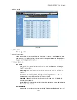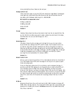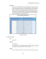
POEGEM24T4SFP
User
Manual
164
Shows
the
switches
current
bridge
priority.
Default:
32768
Designated
Root:
Shows
the
root
bridge
ID
for
this
network
segment.
If
this
switch
is
the
root
bridge,
the
“Designated
Root”
will
be
this
switches
bridge
ID.
Designated
Priority:
Shows
the
current
root
bridge
priority.
Root
Port:
Shows
the
port
number
connected
to
the
root
bridge
with
the
lowest
path
cost.
Root
Path
Cost:
Shows
the
path
cost
between
the
root
port
and
the
designated
port
of
the
root
bridge.
Current
Max.
Age:
Shows
the
current
root
bridge
maximum
age
time.
Maximum
age
time
is
used
to
monitor
if
the
STP
topology
needs
to
change.
When
a
bridge
does
not
receive
a
hello
message
from
a
root
bridge
until
the
maximum
age
time
is
counted
down
to
0,
the
bridge
will
treat
the
root
bridge
as
malfunctioned
and
issue
a
Topology
Change
Notification
(TCN)
BPDU
to
all
other
bridges.
All
bridges
in
the
LAN
will
re
‐
learn
and
determine
who
the
root
bridge
is.
Maximum
Age
time
is
assigned
by
the
root
bridge
in
units
of
seconds.
Default:
20
seconds.
Current
Forward
Delay:
Shows
the
current
root
bridge
forward
delay
time.
The
value
of
the
Forward
Delay
time
is
set
by
the
root.
The
Forward
Delay
time
is
defined
as
the
time
spent
changing
from
the
Listening
state
to
the
Learning
state
or
from
the
Learning
state
to
the
Forwarding
state
of
a
port
in
the
bridge.
Hello
Time:
Shows
the
current
hello
time
of
the
root
bridge.
The
Hello
time
is
a
time
interval
specified
by
the
root
bridge,
used
to
request
all
other
bridges
to
periodically
send
hello
messages
every
“hello
time”
in
seconds
to
the
bridge
attached
to
its
designated
port.
STP
Topology
Change
Count:
Shows
the
time
spent
in
units
of
seconds
since
the
beginning
of
the
Spanning
Tree
Topology
Change
to
the
end
of
the
STP
convergence.
Once
the
STP
change
is
converged,
the
Topology
Change
count
will
be
reset
to
0.
Time
Since
Last
Topology
Change:
Shows
the
accumulated
time
in
units
of
seconds
since
the
last
STP
Topology
Change
was
made.
When
a
Topology
Change
is
initiated
again,
this
counter
will
be
reset
to
0.
Summary of Contents for POEGEM24T4SFP
Page 68: ...POEGEM24T4SFP User Manual 68 Move to the previous page Next Page Move to the next page...
Page 82: ...POEGEM24T4SFP User Manual 82 Fig 3 42 Fig 3 43 Fig 3 44...
Page 89: ...POEGEM24T4SFP User Manual 89 Fig 3 48...
Page 106: ...POEGEM24T4SFP User Manual 106 Fig 3 71 Fig 3 72...
Page 108: ...POEGEM24T4SFP User Manual 108 Fig 3 75 Fig 3 76 Fig 3 77 ARP...
Page 109: ...POEGEM24T4SFP User Manual 109 Fig 3 78 ARP Fig 3 79 ARP Fig 3 80 ARP Fig 3 81 ARP...
Page 110: ...POEGEM24T4SFP User Manual 110 Fig 3 82 ARP Fig 3 83 ARP Fig 3 84 ARP Fig 3 85 ARP...
Page 111: ...POEGEM24T4SFP User Manual 111 Fig 3 86 ARP Fig 3 87 ARP Fig 3 88 ARP Fig 3 89 ARP Fig 3 90 ARP...
Page 112: ...POEGEM24T4SFP User Manual 112 Fig 3 91 IPv4 Fig 3 92 IPv4 Fig 3 93 IPv4...
Page 115: ...POEGEM24T4SFP User Manual 115 Fig 3 105 IPv4 Fig 3 106 IPv4 Fig 3 107 IPv4...
Page 116: ...POEGEM24T4SFP User Manual 116 Fig 3 108 IPv4 Fig 3 109 IPv4 Fig 3 110 IPv4...
Page 117: ...POEGEM24T4SFP User Manual 117 Fig 3 111 IPv4 Fig 3 112 IPv4 Fig 3 113 IPv4 Fig 3 114 IPv4...
Page 118: ...POEGEM24T4SFP User Manual 118 Fig 3 115 IPv4 Fig 3 116 IPv4 Fig 3 117 IPv4...
Page 119: ...POEGEM24T4SFP User Manual 119 Fig 3 118 IPv4 Fig 3 119 IPv4 Fig 3 120 IPv4...
Page 120: ...POEGEM24T4SFP User Manual 120 Fig 3 121 Action Fig 3 122 Rate Limiter...
Page 121: ...POEGEM24T4SFP User Manual 121 Fig 3 123 Port Copy Fig 3 124 DMAC Filter...
Page 211: ...POEGEM24T4SFP User Manual 211 Fig 4 3...
Page 238: ...POEGEM24T4SFP User Manual 238 2 1 3 1 4 1 5 1 POEGEM24T4SFP acl...

