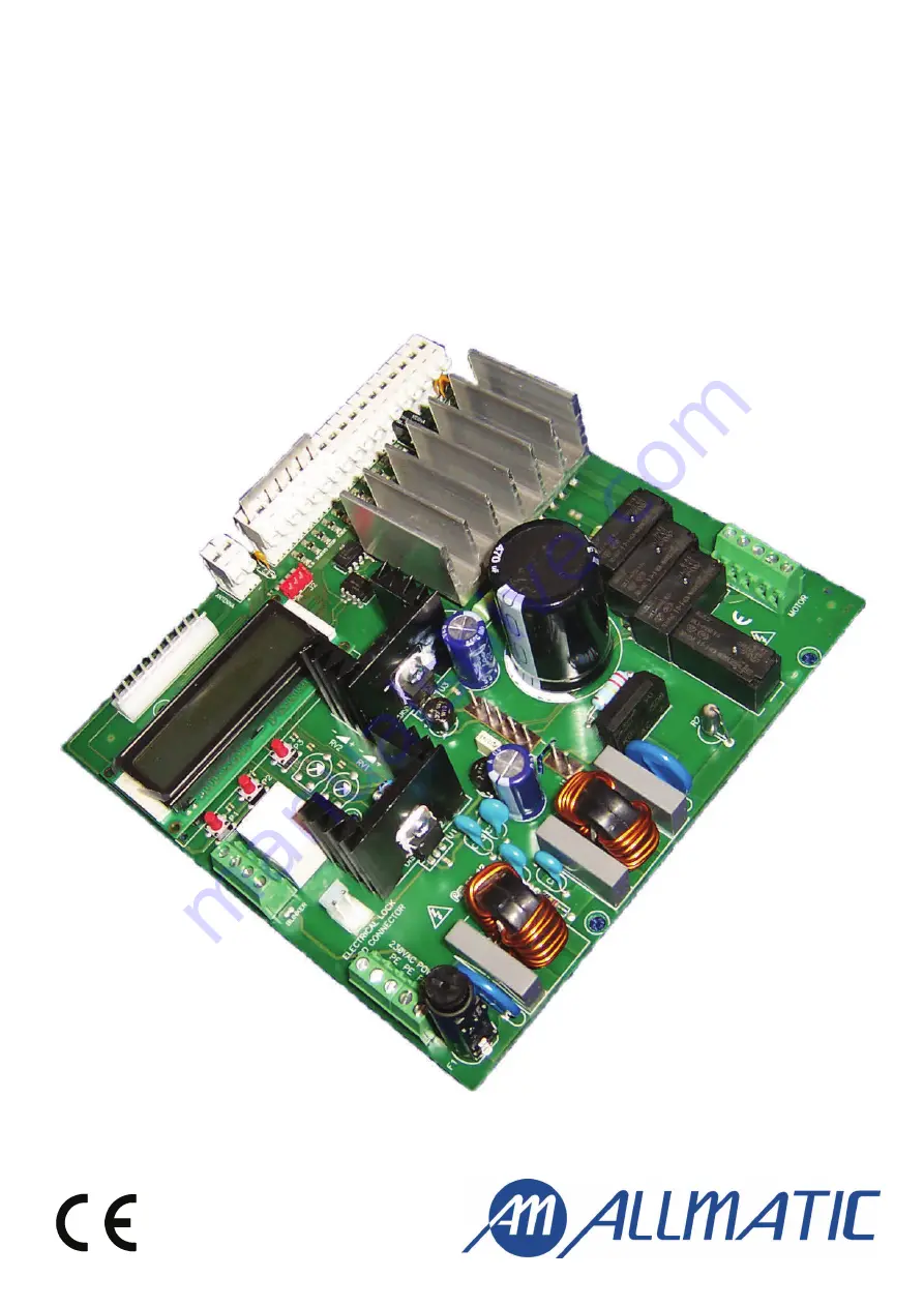
CT INVERTER AM CONTROL UNIT
Programmable control board for sliding gates
with inverter technology
Manual for installation
Compatible from
firmware version
CSMAM02
Page 1: ...CT INVERTER AM CONTROL UNIT Programmable control board for sliding gates with inverter technology Manual for installation Compatible from firmware version CSMAM02...
Page 2: ...ngs It is also equipped with a molex connector for a plug in receiver output for courtesy and flashing light It is possible to connect an additional card R1 to operate an electric lock 1 Introduction...
Page 3: ...inputs if not used INPUT CLOSING LIMIT SWITCH Connect the contact NORMALLY CLOSED of the CLOSING LIMIT SWITCH L S CL between the clamps 3 and 8 of the control board Before activating the installation...
Page 4: ...sure that all the safey devices are correctly cabled and functioning refer to the preliminary checkings section of chap 4 Cable the motor WITHOUT using the capacitor ACCESSORIES OUTPUTS Accessories o...
Page 5: ...of manual accessing to the control board 4 Confirm the entry selected by pressing key P2 The first line of the display shows the present setting for the function selected The second line of the displa...
Page 6: ...hoto Test Functional test of the photocell it is executed before the gate moves OFF disabled ON test activated WARNING supply the photocell with power as shown in the scheme Edge Inv Modality of opera...
Page 7: ...of the wave supplied to the motor Low Speed CL Regulation of the speed of the gate during the closing phase when approaching the end of the run NNN speed expressed in Hz frequency of the wave supplie...
Page 8: ...gate closes then stop the manual motion disconnect the system from the power and reverse the motor connections Then try again If the gate opens then stop the manual motion and go to the following pha...
Page 9: ...cates a possible fault by flashing only once when any key is pressed and also by not moving at all This check is made after the control board receives a command to move but before the control board it...
Page 10: ...alue Encoder If the motor is equipped with a suitable encoder then it is possible to enable the functionalities of the encoder In such way the control board does not work any longer by time but with e...
Page 11: ...blinking Lower the torque supplied to the motor until problem is solved High Tor que OP High Torque OP Lower the speed of the motor until problem is solved High Speed OP High Speed CL 9 1 Low speed m...
Page 12: ...AX cos 0 8 Flashing light output 230 Vac 60W MAX for fixed light without self blinking Courtesy light output 230Vac 100W MAX Auxiliary output only with card R1 Clean contact out put NOT supplied 24Vac...