


Allied Construction Products, LLC www.alliedcp.com
SOM576701_14jan
18
7.0 Care and Maintenance – [cont’d]
Table 7.2 Inspection of Parts
Cause
Remedy
1)
Tool is twisted by
the material
Use conical tool - less
susceptible to twisting
2) Idle
blows
Maintain sufficient feed
force. Stop breaker as soon
as material breaks.
3)
Insufficient
lubrication
Re-lubricate every 2 hours
or if tool shank is dry
4) Side
loading
Align tool at 90° angle to
work surface. Do not pry
with tool.
5) Tool
misalignment
Replace worn tool and / or
bushing
Continued operation with improper technique or worn
parts can risk further damage that may result in costly
repairs.
The most apparent factors contributing to the rate of
wear of front head components include the operator's
technique, lubrication and the abrasiveness of the
material.
Getting the full use out of the tool and bushings will
require regular re-lubrication if it is to remain in usable
condition.
Actively monitor the tool for sufficient lubrication. If
regularly scheduled re-lubrication is not performed,
the condition of parts will quickly deteriorate -
rendering them unusable.
Damage from galling is the result of insufficient
lubrication and/or side loading the tool against the
bushing. Review the frequency, quantity and quality
of lubricant. Shorten re-lubrication interval if the tool is
dry or if chisel paste is not used. Proper operating
techniques will also help minimized wear.
IMPORTANT
Proper selection of lubricant and timely re-
lubrication will allow maximum utilization of the
tool’s working length. Inadequate lubrication, even
for short periods, will result in rapid wear of the tool
and bushings. Re-lubricate every two hours or
sooner if grease is not visible. Use only lubricants
formulated and labeled for use with breakers. Allied
Chisel paste is recommended. When applied
regularly, Chisel Paste is a key element in
extending the service life of bushings and tools.
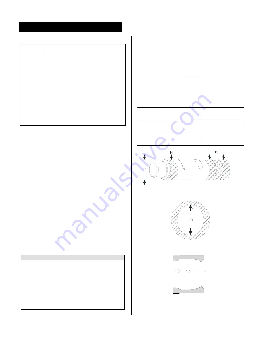
7.4.4 Measuring the Tool and Bushings for Wear
Avoid risk of costly damage to the piston and seals by
regularly measuring the tool and bushing for wear.
Follow wear limits in Table 7.3.
Table 7.3 Wear Limit – Tool, Bushing, Thrust Ring
Units in
inches
[mm]
Gap
Max
"D1"
Tool
OD Min
"D2"
Bushing
ID Max
"D3"
Thrust
Ring
Max
AR110C
.312
[8]
4.25
[108]
4.41
[112]
0.78
[20]
AR120B
.312
[8]
4.64
[118]
4.80
[122]
0.86
[22]
AR130B
.312
[8]
5.04
[128]
5.20
[132]
0.57
[14.5]
AR140B
.312
[8]
5.43
[138]
5.59
[142]
0.70
[18]
Fig 7-5 OD of Tool - Wear is measured at surface
"D2".
Fig 7-6 ID of Bushing - Wear is measured at "D3".
Fig 7-7 Thrust Ring Wear Limit
Summary of Contents for AR110C
Page 60: ...SOM576701_14jan R ...