


33
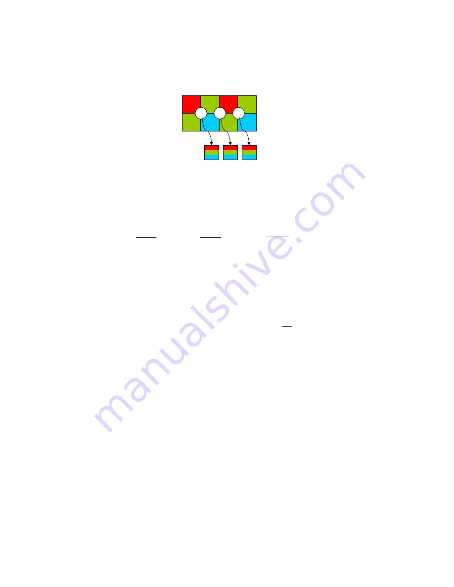
Interpolation (BAYER demosaicing)
In interpolation a red, green or blue value is determined for each pixel. Only two lines
are used for this simple interpolation:
R1
G1
R2
G2
G3
B1
G4
B2
P1
P2
P3
Input:
Output:
Figure 30 Interpolation
1
1
2
3
1
1
1
1
B
P
G
G
P
R
P
blue
green
red
=
+
=
=
1
2
2
4
1
2
2
2
B
P
G
G
P
R
P
blue
green
red
=
+
=
=
2
3
2
4
2
3
2
3
B
P
G
G
P
R
P
blue
green
red
=
+
=
=
Color cameras begin outputting the image in line two and finish in line Y (maximum
image height minus two). This is a side-effect of BAYER demosaicing. The adjustable
maximum image height is also two lines less than in the b/w variant.
L
Please note that on the color camera a black border one pixel wide forms on the
left and right image borders also as a consequence of BAYER demosaicing, because
the image width displayed on the color camera is not scaled down.
Color correction
Color correction is calculated along with YUV conversion and mapped via a matrix like
this.
blue
Cbb
green
Cgb
red
Crb
blue
blue
Cbg
green
Cgg
red
Crg
green
blue
Cbr
green
Cgr
red
Crr
red
⋅
+
⋅
+
⋅
=
⋅
+
⋅
+
⋅
=
⋅
+
⋅
+
⋅
=
*
*
*
On the color camera color correction is also deactivated in Mono8 or Mono16 mode (raw
image transport).
7.7.1
RGB
Æ
YUV conversion
The conversion from RGB to YUV is done using the following formula:
128
082
.
0
420
.
0
498
.
0
128
498
.
0
33
.
0
169
.
0
11
.
0
59
.
0
3
.
0
+
⋅
−
⋅
−
⋅
=
+
⋅
+
⋅
−
⋅
−
=
⋅
+
⋅
+
⋅
=
B
G
R
V
B
G
R
U
B
G
R
Y