


SECTION 2
OPERATIONS
050362
Page 35
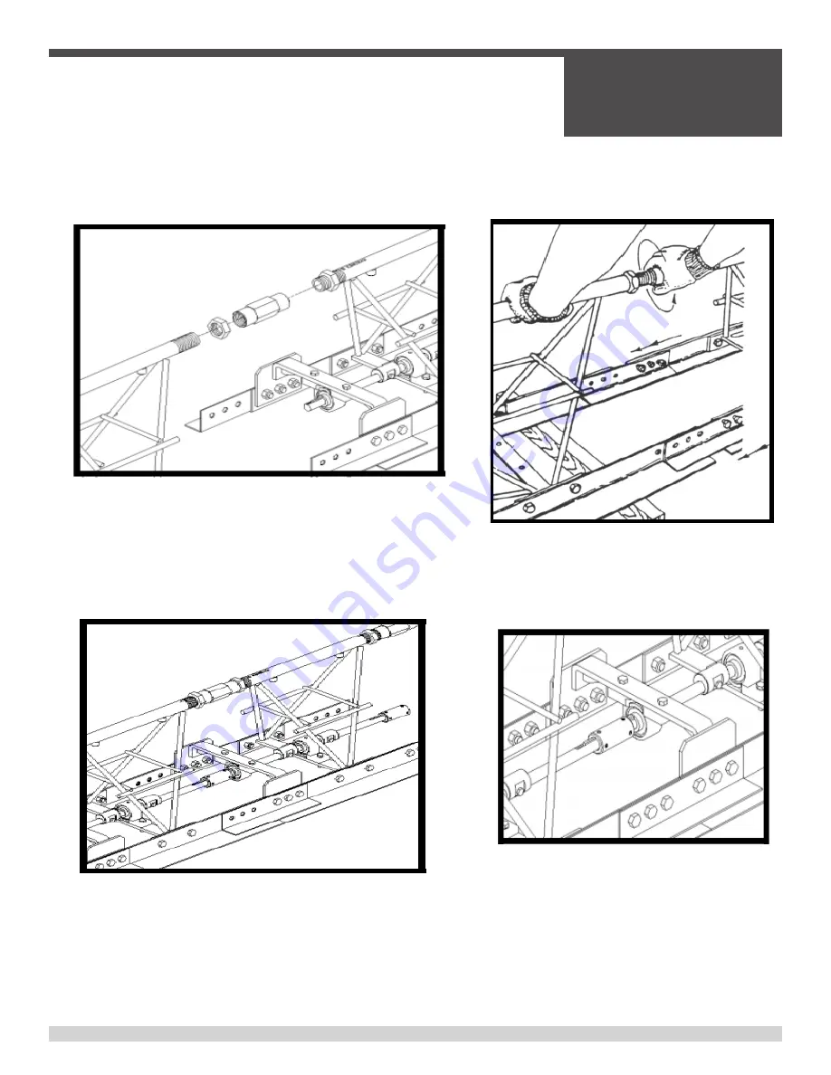
The following figures describe the proper instructions for correctly assembling engine driven screed. Make sure
you follow the instructions in order. If the assembling of your screed is not done in this order, there could be some
problems in trying to maintain floor flatness because your screed is not level. Levelness of your screed is critical!
STEP 1:
Screw jam nuts onto top pipe. Start the top pipe coupler
onto the top pipe of the mating truss section. Only thread the
coupler on about three turns
NOTE:
The right and left hand jam nuts will already be installed
on the screed section.
TIGHTEN JAM NUTS AFTER SCREED IS LEVEL
STEP 2:
Slide screed sections together until top
pipe threads on screed marked “R” line up with
threads in coupler on the screed. Start coupler
on adjoining threads by hand to prevent cross
threading.
STEP 3:
Bearing support bolts should be loose so that
splice plate can move in clearance holes. With 15” adjust-
able wrench, turn top pipe coupler until screed an bull float
blades contact, then back the coupler off slightly so that the
blades touch without tension.
STEP 4:
Tighten bolts on splice plates. Next slide
the shaft coupler on the adjoining section and
tighten the set screws provided. make sure that
the 3/16 key is on the shaft before sliding sec-
tions together. Repeat these steps for attaching all
engine driven screed sections.
Section Assembly
Summary of Contents for SSE12
Page 1: ...OPERATIONS PARTS MANUAL SSE12 SCREED Manual Part 064633 I REVISION B ...
Page 17: ...SECTION 1 SAFETY 050362 Page 17 SECTION 1 SAFETY ...
Page 18: ...SECTION 1 SAFETY 050362 Page 18 State Regulations Proposition 65 Warning ...
Page 19: ...SECTION 1 SAFETY 050362 Page 19 Federal Regulation Respiratory Hazard ...
Page 30: ...SECTION 1 SAFETY 050362 Page 30 Notes ...
Page 31: ...SECTION 2 OPERATIONS 050362 Page 31 SECTION 2 OPERATIONS ...
Page 41: ...SECTION 3 SERVICE 050362 Page 41 SECTION 3 SERVICE ...
Page 43: ...SECTION 4 PARTS 050362 Page 43 SECTION 4 Parts ...
Page 70: ...SECTION 4 PARTS 050362 Page 70 4 13 End Mount Engine Assembly Illustration ...