


Publication 2706-UM016A-EN-P - June 2002
6-8
EtherNet/IP Communications
1.
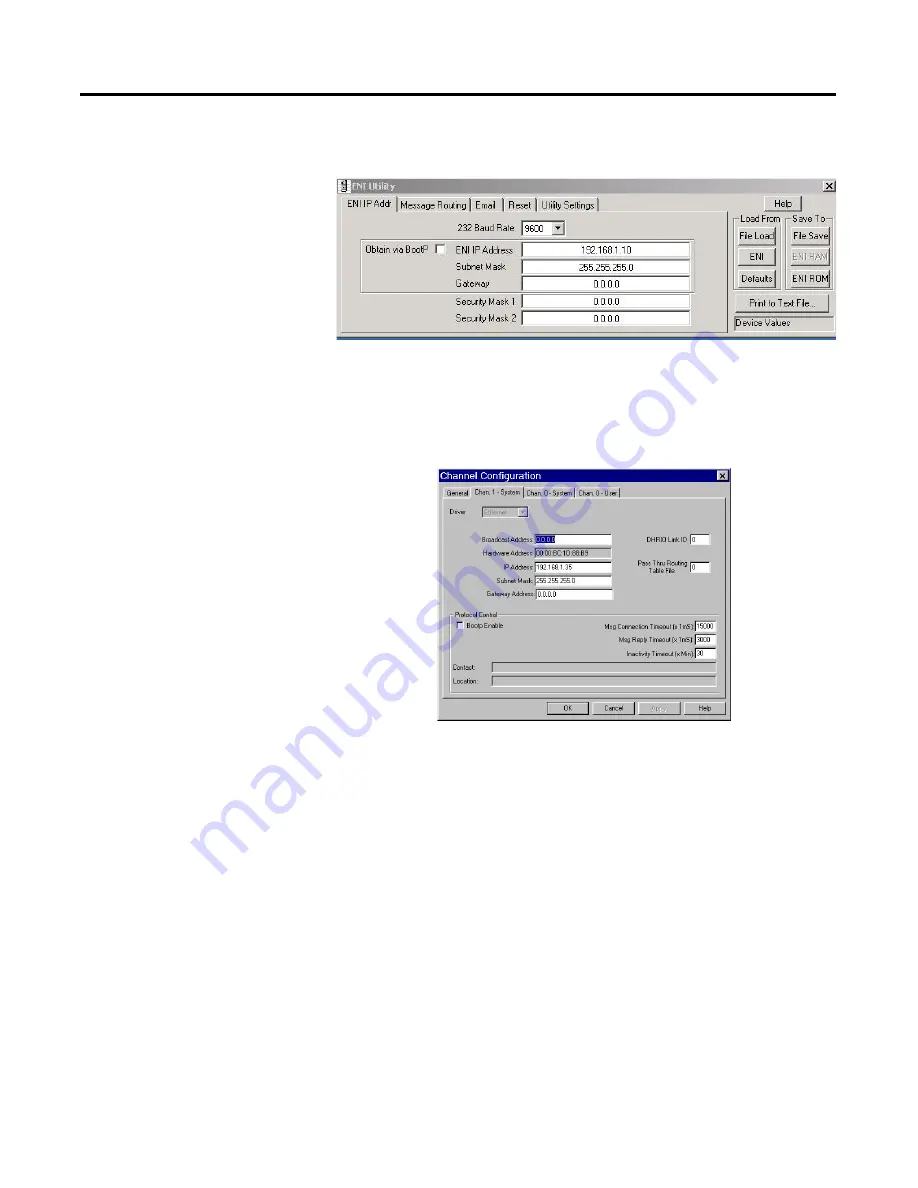
After creating a new application the first thing is to set up the
channel configuration as shown below:
The IP address shown above is the IP address of the SLC 5/05.
2.
Then next thing is to create a file type String (ST). This is where
the user will insert the ASCII/Hex commands.
3.
The last thing is to set up the ladder logic like shown below:
Summary of Contents for InView Marquee 2706-P42
Page 6: ...Publication 2706 UM016A EN P June 2002 Table of Contents iv...
Page 32: ...Publication 2706 UM016A EN P June 2002 1 26 InView Marquee Message Display Installation...
Page 36: ...Publication 2706 UM016A EN P June 2002 2 4 InView System Connectivity...
Page 62: ...Publication 2706 UM016 A EN P June 2002 4 20 DF1 Point to Point Communication...
Page 88: ...Publication 2706 UM016A EN P June 2002 5 26 EtherNet IP Communications with Dual ENI...
Page 103: ...Publication 2706 UM016A EN P June 2002 EtherNet IP Communications 6 15 Allen Bradley Spares...
Page 104: ...Publication 2706 UM016A EN P June 2002 6 16 EtherNet IP Communications...
Page 128: ...Publication 2706 UM016A EN P June 2002 7 24 DeviceNet Communications with Dual DNI...
Page 136: ...Publication 2706 UM016A EN P June 2002 8 8 DeviceNet Communications...
Page 204: ...Publication 2706 UM016A EN P June 2002 A 2 Technical Specifications...
Page 206: ...Publication 2706 UM016A EN P June 2002 B 2 Temperature Protection in NEMA Rated Enclosures...
Page 208: ...Publication 2706 UM016A EN P June 2002 C 2 Catalog Number Explanation...
Page 211: ...Allen Bradley Spares...


