background image

78

Rockwell Automation Publication 842E-UM001C-EN-P -  September 2016

Appendix B

RSLogix 5000® Sample Code

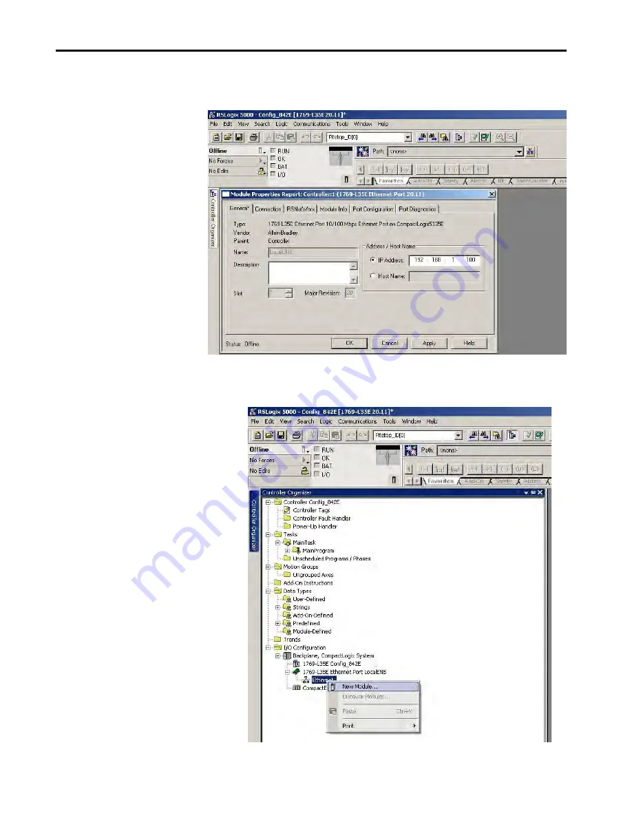
3. Configure the controller IP address, this example uses 192.168.1.100. 

Click 

Apply

, then 

OK

.

Figure 3 

4. Right-click 

Ethernet Network

 and select 

New Module

.

Figure 4 

Summary of Contents for EtherNet/IP 842E-MIP10BA

Page 1: ...SIP4BA 842E SIP5BA 842E SIP6BA 842E SIP7BA 842E SIP8BA 842E SIP9BA 842E SIP10BA 842E SIP11BA 842E SIP12BA 842E MIP1BA 842E MIP2BA 842E MIP3BA 842E MIP4BA 842E MIP5BA 842E MIP6BA 842E MIP7BA 842E MIP8B...

Page 2: ...nformation circuits equipment or software described in this manual Reproduction of the contents of this manual in whole or in part without written permission of Rockwell Automation Inc is prohibited T...

Page 3: ...Electronic Data Sheet File 11 Operating Principle of the Encoder 11 The 842E SIP xxx EtherNet IP Is a Single turn Encoder 11 The 842E MIP xxxEtherNet IP Is a Multi turn Encoder 11 Scalable Resolution...

Page 4: ...Chapter5 Configuring the Encoder for Your EtherNet IP Network Setting the IP Address 43 Assigning the Last Octet in an IP Address Scheme of 192 168 1 xxx Using the Network Address Switches 43 Assigni...

Page 5: ...s 66 Alarms 66 Errors 67 AppendixA Installing the Add on Profile Introduction 69 Performing the Installation 69 AppendixB RSLogix 5000 Sample Code Linear Scaling Example 73 Installing Your Project 74...

Page 6: ...6 Rockwell Automation Publication 842E UM001C EN P September 2016 Table of Contents Notes...

Page 7: ...all and wire your encoder Related Documentation The following documents contain additional information concerning Rockwell Automation products To obtain a copy contact your local Rockwell Automation o...

Page 8: ...8 Rockwell Automation Publication 842E UM001C EN P September 2016 Preface Notes...

Page 9: ...vides considerations for the safety of personnel and systems Due to its design the 842E EtherNet IP can only be operated within an EtherNet IP network It is ATTENTION Onlyauthorizedpersonnelcaninstall...

Page 10: ...l safety stipulations All persons who install operate or maintain the device have to meet the safety regulations The operating instructions must always be available and must always be followed Unquali...

Page 11: ...oders Our accessories help you easily install and efficiently use our encoders What Are the Different Kinds of Encoders Incremental A simple and cost effective solution for a wide variety of applicati...

Page 12: ...olute encoders are either single turn or multi turn Single turn encoders are used if the absolute position of the shaft for one revolution is required Multi turn encoders are used if the absolute posi...

Page 13: ...ng Principle of the Encoder The 842E EtherNet IP encoder acquires the position of rotating axes and outputs the position in the form of a unique digital numeric value Optical acquisition of the rotary...

Page 14: ...30 mm 1 18 in apart High level of resistance to vibration Optimal rotational accuracy Compact design Face mount flange servo flange and blind Hollow shaft ControlFLASH upgradable 18 bit single turn re...

Page 15: ...on the process layer The 842E encoder meets the requirements of the EtherNet IP protocol according to IEC 61784 1 and the requirement of the encoder profile Figure 1 OSI Model Host Layers Layer Functi...

Page 16: ...ed in EtherNet IP for communication that does not need to take place in real time Explicit Messaging uses TCP IP it is used for example to transfer parameters from the PLC to the encoder MAC ID Device...

Page 17: ...module replacement You maintain full control over the route taken by each message which enables you to select alternative paths for the same end device Understanding the Producer Consumer Model The CI...

Page 18: ...e chassis as the controller does not require an RPI because it is not a data producing member of the system it is used only as a bridge to remote modules EtherNet IP Topologies The 842E encoders can b...

Page 19: ...s all devices downstream from the break When this topology is used both Ethernet connections on the encoder are used For the network connection use Link 1 Link 2 or both Figure 5 Device Level Ring Top...

Page 20: ...The nominator can be scaled from 1 2 048 as an integer The default factory setting for the nominator is 2 048 Number of revolutions divisor for the round axis functionality The divisor can be scaled...

Page 21: ...must be set for the functionality to be enabled Attribute ID 0Eh Scaling must be set to 1 Attribute ID 11 h Total resolution must be set to between 1 536 870 912 Attribute ID 7Dh Round axis functiona...

Page 22: ...22 Rockwell Automation Publication 842E UM001C EN P September 2016 Chapter 3 EtherNet IP Overview Figure 8 Attribute 126 7e hex Nominator Figure 9 Attribute 127 7f hex Divisor...

Page 23: ...iew Chapter 3 Figure 10 Attribute 17 11 hex Total measuring range Figure 11 Update your logic to verify that the encoder is in the RUNNING state before executing the message instruction to set the end...

Page 24: ...device provides over EtherNet IP The attributes include the current values of for example a configuration or an input Typical attributes are configuration and status information Service Services are u...

Page 25: ...d for I O messages 7 0x06 Connection manager object Contains connection specific attributes for triggering transport and connection type 1 0x23 Position sensor object Administratesdevice specific data...

Page 26: ...ute_Single Returns the values of one attribute Table 2 Class Services of the Identity Object Attribute ID Access Description Data Type Default Value 1 Get Object revision index UINT 0001h 2 Get Highes...

Page 27: ...ng on the release UINT 01h Get Minor Revision Last part of the revision number for example 02 depending on the release UINT 02h 05h Get Status Device status flags WORD See Table 6 06h Get Serial Numbe...

Page 28: ...onvolatile memory EEPROM failed 0101 Serious error bit 10 or bit 11 1 0110 At least one connection in the Run operating mode 0111 At least one connection exists all in Idle operating mode 1000 1111 Re...

Page 29: ...32 8 102 3 Get Error Position value Warning and alarm flags 32 32 8 9 103 3 Set Get Error Position value Velocity 32 32 32 12 101WS 3 Get Error Position value 32 32 8 102WS 3 Get Error Position value...

Page 30: ...significant byte 2 0 Position value least significant byte 1 Position value 2 Position value 3 Position value most significant byte 4 Warning Alarm 3 0 Position value least significant byte 1 Positio...

Page 31: ...3 Fault header most significant byte 4 Position value least significant byte 5 Position value 6 Position value 7 Position value most significant byte 8 Warning Alarm 103 103WS 0 Fault header least sig...

Page 32: ...M001C EN P September 2016 Chapter 3 EtherNet IP Overview Figure 16 Connections for the Configuration Assembly Config 23h Position Sensor 02h Message Router 01h Identity F6h 06h Connection Manager 04h...

Page 33: ...Not used cw ccw 13 Not used scf 1 14 Not used raf 2 15 Not used 16 Nominator for the number of revolutions CNR_N least significant byte 17 CNR_N 18 CNR_N 19 CNR_N most significant byte 20 Divisor for...

Page 34: ...ices of the Position Sensor Object Num dec Required Optional Access Rule Name Data type Description Default 1 Required implemented Get Revision INT Object revision no 0x00 02 2 Implemented Get Max ins...

Page 35: ...steps per revolution Min 0x00 00 00 01 Max0x00 04 00 00 0x00 04 00 00 17 11 Set NV Total measuring range DINT Total resolution Min Max 0x00 00 00 01 Max 2n Attr 16 18 12 Set NV Position measuring inc...

Page 36: ...V Warnings WORD Flags for warnings 48 30 Get NV Supported warnings WORD Information on supported warnings 0x673C 49 31 Get V Warning flag BOOL Indication of set warning 0 OK 1 Warning Flag 50 32 Get N...

Page 37: ...rent value A INT Max light emitting diode current A 1 500 116 74 Get NV Min currentvalue A INT Min light emitting diode current A 1 500 117 0X75 Get V Direction change counter UDINT Direction change c...

Page 38: ...filter integration time UDINT Acceleration filter taps integration time 0 128 1 131 0x83 Set NV Acceleration filter bandwidth UDINT Controlsthebandwidthofthelowpass filter that is applied to the raw a...

Page 39: ...h a Solid Shaft 1 Be sure to select the proper size flexible coupling clamp to mate to the encoder shaft for example 845 FC See our website at http ab rockwellautomation com Motion Control Encoders fo...

Page 40: ...mount rests on the machine surface 3 Hold encoder firmly and mark the two mounting holes If mounting holes exist proceed to Step 6 4 Slide the encoder off To accept M4 or equivalent screws drill and...

Page 41: ...75 in Servo flange 6 x 10 mm 0 24 x 0 39 in Blind hollow shaft 8 10 12 15 mm and 1 4 1 2 3 8 5 8 in ATTENTION Switch off the power supply The machine system could unintentionally start while you are c...

Page 42: ...IP address on page 45 Pin Signal Mating Cable Wire Color Function 1 Versus Brown Supply voltage 10 30V DC 2 White Do not use 3 GND Blue 0V DC ground 4 Black Do not use Table 1 Voltage Supply Pin Sign...

Page 43: ...pecifications Operating voltage 10 30V DC Power consumption 3 W Load current 200 mA Resolution per revolution 262 144 Revolutions 4 096 Repeat accuracy 0 002 Error limit 0 03 Code direction CW or CCW...

Page 44: ...44 Rockwell Automation Publication 842E UM001C EN P September 2016 Chapter 4 Installation Notes...

Page 45: ...er 2 Use the network address switches to enable BOOTP DHCP and use a BOOTP utility or DHCP server to assign the IP address of the unit on powerup Assigning the Last Octet in an IP Address Scheme of 19...

Page 46: ...rom a BOOTP DHCP server 4 If the encoder MAC ID is in the relationship list the BOOTP DHCP server assigns the associated IP address to the corresponding MAC ID Figure 2 Setting of Network Address Swit...

Page 47: ...etain the IP address at the next power cycle Wait for the status message to show that the command was successfully sent If the message does not appear repeat this step Figure 3 6 Click File Save As to...

Page 48: ...48 Rockwell Automation Publication 842E UM001C EN P September 2016 Chapter 5 Configuring the Encoder for Your EtherNet IP Network Notes...

Page 49: ...version 20 Example Installing the Hardware In this example a CompactLogix chassis contains the L35E processor in slot 1 and a built in EtherNet IP connection The encoder is connected to a Stratix 600...

Page 50: ...tion Both options are explained in detail including views of software screens in this chapter CheckingtheIntegrationinEtherNet IPViaRSLinx Classic With the aid of the tool RSLinx Classic you can again...

Page 51: ...ddress Figure 3 4 Install the Add on Profile according to the instructions in Appendix A page 71 Installing the Add on Profile in RSLogix 5000 After you install the encoder Add on Profile see Appendix...

Page 52: ...ation 842E UM001C EN P September 2016 Chapter 6 Configuring the 842 E Encoder Using RSLogix 5000 3 Enter the new controller information Figure 5 4 Right click on the Ethernet port of the controller an...

Page 53: ...1 Enter a name for the encoder In this example the name is Encoder_1 You have multiple encoders or other modules so be sure to give each a brief but descriptive name The name that you assign to the e...

Page 54: ...ate network is used click the Private Network radio button Enter a value of 1 254 for the last segment octet of the address Be sure not to duplicate the address of an existing device In the preceding...

Page 55: ...ion 842E UM001C EN P September 2016 55 Configuring the 842 E Encoder Using RSLogix 5000 Chapter 6 Figure 10 Click the Host Name radio button and type in the name of the host In the example below the h...

Page 56: ...pull down menu allows you to select either a Data or Listen Only connection see definitions below The Input data pull down menu allows you to select position position status or position velocity see...

Page 57: ...al but if no data is received the controller asks the encoder for a status update Minimum setting is 4 ms and the maximum setting is 750 ms Inhibit Module When checked the controller ignores all infor...

Page 58: ...vendor product type product code revision level serial number and product name The right panel Status shows the fault status internal state that is run mode and whether the file is owned and Module I...

Page 59: ...g makes it possible to scale the steps per revolution and the total resolution see Linear Scaling Example on page 75 in Appendix B If the Enable Scaling box is checked the values can be entered for th...

Page 60: ...mber 2016 Chapter 6 Configuring the 842 E Encoder Using RSLogix 5000 Internet Protocol Tab Figure 16 For this user manual the user is expected to use a private address that is an address of 192 168 1...

Page 61: ...populated when the controller goes online Network Topology Displays the current network topology as either linear star or ring Network Status Displays the current network status as normal ring fault...

Page 62: ...ustment function during commissioning Rather it allocates a specific value to the mechanical rotary position of the 842E encoder For example the encoder zero position can be adjusted to the zero point...

Page 63: ...The categories of tags appear The tag name is composed of the encoder name followed by a C for configuration I for input ConfigurationImageTableandTags Expand Enc_1 C by clicking Showing the configura...

Page 64: ...Fault status of the encoder Enc_1 I Position Position status of the encoder If position status is selected from the input data selection in the encoder definition you also see alarms and warning statu...

Page 65: ...er Five status indicators provide status information on the back of the encoder The figure shows their location and the tables describe their status Figure 1 Read the status indicators according to th...

Page 66: ...ce operational Green blinking Standby device not configured no IP address assigned Red blinking Warning but device still operational or Firmware update in progress Red Error device not operational Gre...

Page 67: ...rs Via EtherNet IP Within EtherNet IP warnings alarms and errors can be retrieved using implicit messages and also explicit messages Alarms and warnings for the encoder can be read via the position se...

Page 68: ...ded OK Exceeded 1 Light control reserve Status indicator current critical OK Out of Range 2 CPU watchdog Notimplemented Always 0 3 Operating time limit warning Operating time limit is reached Always 0...

Page 69: ...is out of range 1 Over temperature sensor Temperature value of the sensor is out of range 2 Light control reserve Indicator current is not correct 3 Voltage detection Over Under voltage detection fall...

Page 70: ...uest error connection type multi cast uni cast not supported Check whether the configuration assembly instance 100 of the Assembly Object is activated If yes check whether the configuration data are c...

Page 71: ...n Profile simplifies the setup of devices because it presents the necessary fields in an organized fashion The AOP allows you to install and configure your systems in a quick and efficient manner The...

Page 72: ...mation Publication 842E UM001C EN P September 2016 Appendix A Installing the Add on Profile 5 At the welcome screen click Next Figure 2 6 To accept the licensing terms click the radio button then clic...

Page 73: ...utomation Publication 842E UM001C EN P September 2016 73 Installing the Add on Profile Appendix A 7 Click the Install radio button and then click Next Figure 4 8 Click Install to begin the installatio...

Page 74: ...l Automation Publication 842E UM001C EN P September 2016 Appendix A Installing the Add on Profile 9 Click Next to install the Add on Profile files Figure 6 10 Click Finish to complete the installation...

Page 75: ...ge 91 Linear Scaling Example A linear cart is to be controlled using ball screw slide The cart will stop after 1 m 3 28 ft of travel for loading and unloading For precise measurement of the distance b...

Page 76: ...2 Set Counts per Revolution to 200 3 Total Measuring Range is 51 200 4 Position the slide encoder to a known start position 5 Set the preset value The encoder retains the preset value through a machi...

Page 77: ...kwell Automation Publication 842E UM001C EN P September 2016 77 RSLogix 5000 Sample Code Appendix B 2 In the controller organizer right click Ethernet Communication Adapter and select Properties Figur...

Page 78: ...on 842E UM001C EN P September 2016 Appendix B RSLogix 5000 Sample Code 3 Configure the controller IP address this example uses 192 168 1 100 Click Apply then OK Figure 3 4 Right click Ethernet Network...

Page 79: ...he encoder Add on Profiles under specialty modules Select the Add on Profile for either Multi turn Encoder or Single turn Encoder then click Create Figure 5 6 The encoder Add on Profile configuration...

Page 80: ...tion Publication 842E UM001C EN P September 2016 Appendix B RSLogix 5000 Sample Code Figure 6 7 Click the Configuration tab and set it up as shown per the linear scaling example on page 75 Click Apply...

Page 81: ...842E UM001C EN P September 2016 81 RSLogix 5000 Sample Code Appendix B 8 The encoder can now be seen as configured on the Ethernet network in the controller organizer Figure 8 9 The project can then...

Page 82: ...ore the preset value it applies the preset value to the encoder position value The following program fragment sends an explicit message and confirms the message reception 1 Create a message data type...

Page 83: ...onfigure it double click the gray box on the message instruction Figure 10 3 Use the Position Sensor Object to find the values you want to use to send an explicit message In the Configuration tab sele...

Page 84: ...blication 842E UM001C EN P September 2016 Appendix B RSLogix 5000 Sample Code 4 In the Communication tab browse to the encoder on the Ethernet network then click OK Figure 11 5 The Tag tab is populate...

Page 85: ...Automation Publication 842E UM001C EN P September 2016 85 RSLogix 5000 Sample Code Appendix B Figure 12 6 To initialize the message instruction add a normally open contact and a one shot instruction F...

Page 86: ...et contact the message instruction presets the current count value of the encoder The position value is changed to the preset value you set Figure 14 Using an Explicit Message Configuration to Read Pr...

Page 87: ...N P September 2016 87 RSLogix 5000 Sample Code Appendix B Figure 15 2 Add an MSG instruction to the program and browse to the Read_Preset data type created in step 1 To configure it double click the g...

Page 88: ...guration tab select Message type CIP generic Service type Get attribute single Service Code automatically populated Source element Preset_Value_Read browse to this tag Instance 1 Class 23 Attribute 13...

Page 89: ...842E UM001C EN P September 2016 89 RSLogix 5000 Sample Code Appendix B 5 The Tag tab is populated for the Read_Preset Figure 18 6 To initialize the message instruction add a normally open contact and...

Page 90: ...ion Publication 842E UM001C EN P September 2016 Appendix B RSLogix 5000 Sample Code 7 Toggle the Get_preset contact the message instruction returns the preset value form the encoder into Preset_Value_...

Page 91: ...B Using an Explicit Message Configuration to Obtain the Encoder Runtime in Seconds This example is similar to the previous one Using an Explicit Message Configuration to Read Preset Encoder Value on p...

Page 92: ...e Run_Time_Message data type created in step 1 To configure the message instruction double click the gray box Figure 22 3 In the Configuration tab select Message type CIP Generic Service Type Get Attr...

Page 93: ...ation 842E UM001C EN P September 2016 93 RSLogix 5000 Sample Code Appendix B 4 In the Communication tab browse to the encoder on the Ethernet network then click OK Figure 23 5 The Tag tab is populated...

Page 94: ...gix 5000 Sample Code Figure 24 6 To initialize the message instruction add a normally open contact and a one shot instruction Figure 25 Toggle the Get_Run_Time contact to initiate the message instruct...

Page 95: ...Rockwell Automation Publication 842E UM001C EN P September 2016 95 RSLogix 5000 Sample Code Appendix B Notes...

Page 96: ...Codes Find the Direct Dial Code for your product Use the code to route your call directly to a technical support engineer http www rockwellautomation com global support direct dial page Literature Li...

Reviews: