background image

Publication 2098-IN003E-EN-P — April 2004

2-32

Ultra3000 Connector Data

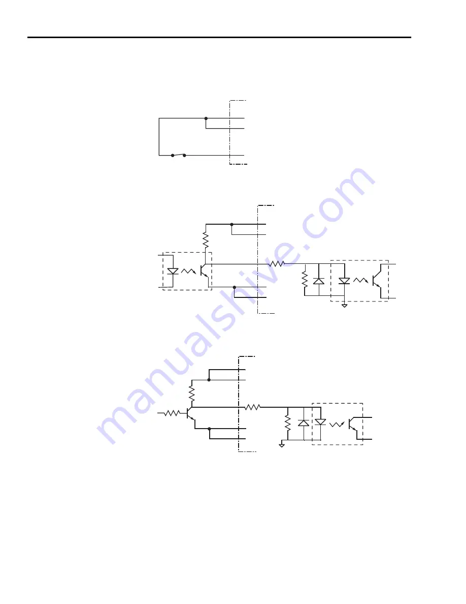
Input Interface Examples for Active Low Inputs

Figure 2.21
Drive Input Connected to Normally Closed Switch 

Figure 2.22
Drive Input Connected to Opto-Isolator 

Figure 2.23
Drive Input Connected to NPN Transistor 

CN1-29

CN1-30

CN1-31
through CN1-38

Ultra3000 Drive

IOPWR

IOPWR

2.7k

Ω

1k

Ω

CN1-29

CN1-30

CN1-27

CN1-28

CN1-31

through CN1-38

R

L

Ultra3000 Drive

IOCOM

IOCOM

IOCOM

IOPWR

IOPWR

2.7k

Ω

1k

Ω

CN1-29

CN1-30

R

L

CN1-27

CN1-28

CN1-31

through CN1-38

Ultra3000 Drive

IOCOM

IOCOM

IOCOM

IOPWR

IOPWR

Summary of Contents for 2098-DSD-005

Page 1: ...5 010 and 020 2098 DSD xxxX 2098 DSD xxx SE 2098 DSD xxx DN 2098 DSD xxxX DN 2098 DSD 030 075 and 150 2098 DSD xxxX 2098 DSD xxx SE 2098 DSD xxx DN 2098 DSD xxxX DN 2098 DSD HV030 HV050 HV100 HV150 an...

Page 2: ...s that should be taken into consideration when applying products such as those described in this publication Reproduction of the contents of this copyrighted publication in whole or part without writt...

Page 3: ...porated into this installation manual in the section immediately following this Summary of Changes section and before the Table of Contents Before using this installation manual read and understand th...

Page 4: ...II Rockwell Automation Publication 2098 IN003E EN P March 2012 Summary of Changes Notes...

Page 5: ...2098 DSD xxxX DN 2098 DSD HV030 HV050 HV100 HV150 and HV220 2098 DSD xxxX 2098 DSD xxxSE 2098 DSD xxx DN 2098 DSD xxxX DN About This Publication This document updates information about the Ultra3000...

Page 6: ...XMT Note Pin outs vary by manufacturer This example uses a B B 485 adapter Drive 1 Drive 2 Drive n Error Code Problem or Symptom Possible Cause Action Solution E02 Velocity exceeds position rollover...

Page 7: ...pk 2 5 A 5 A 10 A Intermittent output current 0 pk 7 5 A 15 A 30 A Bus capacitance 1410 F 1880 F 1880 F Internal shunt resistance N A N A N A Shunt on N A N A N A Shunt off N A N A N A Bus overvoltag...

Page 8: ...A 75 A 150 A Bus capacitance 2820 F 4290 F 7520 F Internal shunt resistance 35 16 5 9 1 Shunt on 420V dc 420V dc 420V dc Shunt off 402V dc 402V dc 402V dc Bus overvoltage 452V dc 452V dc 452V dc Inter...

Page 9: ...W 200 W 16 kW 200 W 25 6 kW 400 W 32 kW External Shunt Resistance 0 5 Continuous power Peak power 120 3 kW 5 3 kW 40 10 kW 16 kW 25 15 kW 25 6 kW 20 22 kW 32 kW Energy Absorption Capability 230V ac in...

Page 10: ...e ac EMC line filter as close to the drive as possible and do not route very dirty wires in wireway refer to Establishing Noise Zones on page 1 13 If routing in wireway is unavoidable use shielded cab...

Page 11: ...098 DSD 075x xx and 150x xx Note 13 AC Input Power Connections Motor Power Connections Three phase AC Line Filter Note 7 Input Fusing Note 4 5 Three phase Input 100 240V ac rms Fused Disconnect or Cir...

Page 12: ...SD HVxxx xx and HVxxxX xx Note 14 AC Input Power Connections Motor Power Connections Three phase AC Line Filter Note 7 Three phase Input 230 480V ac rms Fused Disconnect or Circuit Breaker Note 1 Isol...

Page 13: ...RANGE 11 S2 S3 COM YELLOW WHT YELLOW 13 8 3 4 5 6 1 2 14 15 16 17 12 11 13 9 10 Motor Brake Motor Power TB1 Cable Shield Clamp Note 9 Note 19 Motor Feedback 15 pin Connector CN2 Three Phase Motor Powe...

Page 14: ...BRN BLK BLU GN YL U V W Motor Brake Motor Power TB1 Cable Shield Clamp Note 9 Note 19 Motor Feedback 15 pin Connector CN2 Three Phase Motor Power Motor Feedback Thermostat 9101 0330 Brake Cable Conne...

Page 15: ...GND 43 44 24V COM 1 BLK 2 BLK 3 BLK GN YL U V W Motor Brake Motor Power TB1 Cable Shield Clamp Note 9 Note 19 Motor Feedback 15 pin Connector CN2 Three Phase Motor Power Motor Feedback User Supplied 2...

Page 16: ...to Rockwell Automation are property of their respective companies Compatible Brake Motors Coil Current Compatible Brake Motors Coil Current MPL x15xx 1 0 48 A 1326AB B4xxx 0 88 A MPL x2xx 1 0 51 A F...

Page 17: ...Modules 1 5 System Mounting Requirements 1 6 Ventilation Requirements 1 7 Sizing an Enclosure 1 8 Transformer Sizing 1 8 Fuse Sizing 1 10 HF Bonding Your System 1 10 Bonding Modules 1 11 Bonding Multi...

Page 18: ...r 3 Connecting Your Ultra3000 Chapter Objectives 3 1 Understanding Basic Wiring Requirements 3 1 Building Your Own Cables 3 2 Routing Power and Signal Wiring 3 2 Determining Your Type of Input Power 3...

Page 19: ...ntactor Ratings A 7 Power Dissipation Specifications A 7 Ultra3000 General Specifications A 8 Physical and Environmental Specifications A 8 Control Specifications A 8 Inputs and Outputs Specifications...

Page 20: ...C Catalog Numbers and Accessories Chapter Objectives C 1 Ultra3000 Drives C 2 Software C 2 AC Line Filters C 3 External Shunt Kits C 3 Cables C 4 Motor Power Cables C 4 Motor Feedback Cables C 5 MP S...

Page 21: ...ic understanding of the Ultra3000 contact your local Allen Bradley representative for information on available training courses before using this product Purpose of this Manual This manual provides th...

Page 22: ...se a clean dry location Maintain an ambient temperature range of 40 to 70 C 40 to 158 F Maintain a relative humidity range of 5 to 95 non condensing Store it where it cannot be exposed to a corrosive...

Page 23: ...tructions 1756 IN572x EN P ControlLogix Analog Encoder Servo module installation instructions Analog Encoder AE Servo Module Installation Instructions 1756 IN047x EN P SoftLogix SERCOS interface PCI c...

Page 24: ...roughout the United States alone plus Allen Bradley representatives in every major country in the world Local Product Support Contact your local Allen Bradley representative for Sales and order suppor...

Page 25: ...Your System Planning Your Panel Layout Mounting Your Ultra3000 Drive ATTENTION The following information is a guideline for proper installation The National Electrical Code and any other governing re...

Page 26: ...61800 3 Adjustable Speed Electrical Power Drive Systems Part 3 EMC Product Standard including specific test methods The product described in this manual is intended for use in an industrial environmen...

Page 27: ...iceNet and Ultra3000 with indexing DeviceNet available with 3 5 10 15 and 22 kW continuous output with 460V input power ControlLogix SoftLogix Platforms 1756 MxxSE module 1784 PM16SE PCI card The SERC...

Page 28: ...sis Output RSLogix 5000 Commissioning and Communications Input ControlLogix Controller Encoder Feedback Motor Power MP Series Servo Motor Ultra3000 SE SERCOS Fiber Optic Ring Encoder Feedback Motor Po...

Page 29: ...es Each Ultra3000 ships with the following One Ultra3000 drive One installation manual publication 2098 IN003x EN P Remove all packing material wedges and braces from within and around the components...

Page 30: ...face that won t be subjected to shock vibration moisture oil mist dust or corrosive vapors You need to maintain minimum clearances refer to Figure 1 4 for proper airflow easy module access and proper...

Page 31: ...rflow and installation 50 8 mm 2 0 in clearance for airflow and installation Allow 12 7 mm 0 5 in side clearance Allow 12 7 mm 0 5 in side clearance Motor cable entry area for ground clamp Minimum cab...

Page 32: ...from each calculation to get a system kW total Definitions kW power or real power KVA apparent power Transformer KVA rating Sum of average output power of each axis x 2 0 Metric Standard English Wher...

Page 33: ...sure of the exact speed and torque in your application another approach is to look at the speed torque curve for your Ultra3000 motor combination and use the values for the worst case continuous spee...

Page 34: ...For example if 60 C 140 F wire is used the fuse should not exceed 8A If 75 C 167 F wire is used the fuse should not exceed 13A Refer to Fuse Specifications in Appendix A for fuse examples HF Bonding Y...

Page 35: ...the drive and subpanel construct your subpanel out of zinc plated paint free steel Stud mounting the subpanel to the enclosure back wall Stud mounting a ground bus or chassis to the subpanel Subpanel...

Page 36: ...ommended bonding practices Figure 1 6 Multiple Subpanels and Cabinet Planning Your Panel Layout This section outlines the practices which minimize the possibility of noise related failures as they app...

Page 37: ...ty cables enter a wireway The SERCOS fiber optic cables are immune to electrical noise Figure 1 7 Establishing Noise Zones 1 If I O cable contains dirty relay wires route cable with motor power wires...

Page 38: ...gories for the Ultra3000 The table below indicates the zoning requirements of cables connecting to the Ultra3000 1 D D C EMC Filter Spare Slot s Dirty Wireway Clean Wireway Route dirty wireways direct...

Page 39: ...the Ultra3000 as possible Good HF bonding to the panel is critical For painted panels refer to Figure 1 5 Segregate input and output wiring as far as possible Wire Cable Connector Zone Method Very Dir...

Page 40: ...IN 1394 300W SHUNT MODULE ALLEN BRADLEY FOR USE WITH 1394 SJT22 X SYSTEM MODULE CAT PART SER INPUT DC INPUT AC FOR FUSE REPLACEMENT USE BUSSMAN CAT NO R D D VD D D D Motor DC Bus 100 240 VAC 50 60 Hz...

Page 41: ...Shunt Module BULLETIN 1394 300W SHUNT MODULE ALLEN BRADLEY FOR USE WITH 1394 SJT22 X SYSTEM MODULE CAT PART SER INPUT DC INPUT AC FOR FUSE REPLACEMENT USE BUSSMAN CAT NO R Motor DC Bus 100 240 VAC 50...

Page 42: ...00 to the cabinet first using the upper mounting slots of the drive and then the lower The recommended mounting hardware is M5 metric 1 4 20 or 10 MS bolts Observe bonding techniques as described in H...

Page 43: ...e D shell type connectors Designator Description Connector CN1 User Input Output 44 pin high density D shell CN2 Motor Feedback 15 pin high density D shell CN3 Serial Port 9 pin standard D shell TB DC...

Page 44: ...5 Pin 1 Pin 10 Pin 5 Pin 30 Pin 44 Pin 1 Pin 15 Pin 16 Pin 31 Pin 6 Pin 9 Pin 1 Pin 5 CN1 44 pin User I O Connector CN2 15 pin Motor Feedback Connector CN3 9 pin Serial Port Connector Logic Power LED...

Page 45: ...r Encoder Ch B BM 34 Digital Input 4 INPUT4 13 Unbuffered Motor Encoder Ch B BM 35 Digital Input 5 INPUT5 14 Unbuffered Motor Encoder Ch I IM 36 Digital Input 6 INPUT6 15 Unbuffered Motor Encoder Ch I...

Page 46: ...B1 TB2 Pin 11 Pin 6 Pin 15 Pin 1 Pin 10 Pin 5 Pin 30 Pin 44 Pin 1 Pin 15 Pin 16 Pin 31 Pin 6 Pin 9 Pin 1 Pin 5 AC Input Power Connections Motor Power Connections Passive Shunt Resistor Connections Sev...

Page 47: ...Digital Input 4 INPUT4 13 Unbuffered Motor Encoder Ch B BM 35 Digital Input 5 INPUT5 14 Unbuffered Motor Encoder Ch I IM 36 Digital Input 6 INPUT6 15 Unbuffered Motor Encoder Ch I IM 37 Digital Input...

Page 48: ...2 3 TB2 TB1 Pin 11 Pin 6 Pin 15 Pin 1 Pin 10 Pin 5 Pin 30 Pin 44 Pin 1 Pin 15 Pin 16 Pin 31 Pin 6 Pin 9 Pin 1 Pin 5 AC Input Power Connections Motor Power Connections Passive Shunt Resistor Connectio...

Page 49: ...Digital Input 4 INPUT4 13 Unbuffered Motor Encoder Ch B BM 35 Digital Input 5 INPUT5 14 Unbuffered Motor Encoder Ch I IM 36 Digital Input 6 INPUT6 15 Unbuffered Motor Encoder Ch I IM 37 Digital Input...

Page 50: ...G N A D Hazardous voltage exists after power down TB1 Pin 11 Pin 6 Pin 15 Pin 1 Pin 10 Pin 5 Pin 30 Pin 44 Pin 1 Pin 15 Pin 16 Pin 31 Pin 6 Pin 9 Pin 1 Pin 5 AC Input Power Connections Motor Power Con...

Page 51: ...Digital Input 4 INPUT4 13 Unbuffered Motor Encoder Ch B BM 35 Digital Input 5 INPUT5 14 Unbuffered Motor Encoder Ch I IM 36 Digital Input 6 INPUT6 15 Unbuffered Motor Encoder Ch I IM 37 Digital Input...

Page 52: ...16 Pin 31 Pin 6 Pin 9 Pin 1 Pin 5 8 CN1 44 pin User I O Connector CN2 15 pin Motor Feedback Connector CN3 9 pin Serial Port Connector Logic Power LED Seven Segment Status LED DC Bus Connections for Ac...

Page 53: ...11 Unbuffered Motor Encoder Ch A AM 33 Registration Sensor 1 Input REG1 12 Unbuffered Motor Encoder Ch B BM 34 Registration Sensor 2 Input REG2 13 Unbuffered Motor Encoder Ch B BM 35 Reserved 14 Unbu...

Page 54: ...4 Pin 1 Pin 15 Pin 16 Pin 31 Pin 6 Pin 9 Pin 1 Pin 5 8 AC Input Power Connections Motor Power Connections Passive Shunt Resistor Connections Seven Segment Status LED Logic Power LED CN3 9 pin Serial P...

Page 55: ...Encoder Ch A AM 33 Registration Sensor 1 Input REG1 12 Unbuffered Motor Encoder Ch B BM 34 Registration Sensor 2 Input REG2 13 Unbuffered Motor Encoder Ch B BM 35 Reserved 14 Unbuffered Motor Encoder...

Page 56: ...in 30 Pin 44 Pin 1 Pin 15 Pin 16 Pin 31 Pin 6 Pin 9 Pin 1 Pin 5 8 AC Input Power Connections Motor Power Connections Passive Shunt Resistor Connections Seven Segment Status LED Logic Power LED CN3 9 p...

Page 57: ...Encoder Ch A AM 33 Registration Sensor 1 Input REG1 12 Unbuffered Motor Encoder Ch B BM 34 Registration Sensor 2 Input REG2 13 Unbuffered Motor Encoder Ch B BM 35 Reserved 14 Unbuffered Motor Encoder...

Page 58: ...11 Pin 6 Pin 15 Pin 1 Pin 10 Pin 5 Pin 30 Pin 44 Pin 1 Pin 15 Pin 16 Pin 31 Pin 6 Pin 9 Pin 1 Pin 5 8 AC Input Power Connections Motor Power Connections Passive Shunt Resistor Connections Seven Segmen...

Page 59: ...Encoder Ch A AM 33 Registration Sensor 1 Input REG1 12 Unbuffered Motor Encoder Ch B BM 34 Registration Sensor 2 Input REG2 13 Unbuffered Motor Encoder Ch B BM 35 Reserved 14 Unbuffered Motor Encoder...

Page 60: ...n 30 Pin 44 Pin 1 Pin 15 Pin 16 Pin 31 Pin 6 Pin 9 Pin 1 Pin 5 AC Input Power Connections Motor Power Connections DC Bus Connections for Active Shunt Resistor Kit Seven Segment Status LED Logic Power...

Page 61: ...r Encoder Ch B BM 34 Digital Input 4 INPUT4 13 Unbuffered Motor Encoder Ch B BM 35 Digital Input 5 INPUT5 14 Unbuffered Motor Encoder Ch I IM 36 Digital Input 6 INPUT6 15 Unbuffered Motor Encoder Ch I...

Page 62: ...n 30 Pin 44 Pin 1 Pin 15 Pin 16 Pin 31 Pin 6 Pin 9 Pin 1 Pin 5 V Can_L Shield Can_H V AC Input Power Connections Motor Power Connections Passive Shunt Resistor Connections Seven Segment Status LED Log...

Page 63: ...Digital Input 4 INPUT4 13 Unbuffered Motor Encoder Ch B BM 35 Digital Input 5 INPUT5 14 Unbuffered Motor Encoder Ch I IM 36 Digital Input 6 INPUT6 15 Unbuffered Motor Encoder Ch I IM 37 Digital Input...

Page 64: ...n 10 Pin 5 Pin 30 Pin 44 Pin 1 Pin 15 Pin 16 Pin 31 Pin 6 Pin 9 Pin 1 Pin 5 V Can_L Shield Can_H V AC Input Power Connections Motor Power Connections Passive Shunt Resistor Connections Seven Segment S...

Page 65: ...Digital Input 4 INPUT4 13 Unbuffered Motor Encoder Ch B BM 35 Digital Input 5 INPUT5 14 Unbuffered Motor Encoder Ch I IM 36 Digital Input 6 INPUT6 15 Unbuffered Motor Encoder Ch I IM 37 Digital Input...

Page 66: ...kB 250kB 125kB AUTO PGM V Can_L Shield 00 63 PGM Pin 11 Pin 6 Pin 15 Pin 1 Pin 10 Pin 5 Pin 30 Pin 44 Pin 1 Pin 15 Pin 16 Pin 31 Pin 6 Pin 9 Pin 1 Pin 5 AC Input Power Connections Motor Power Connecti...

Page 67: ...Digital Input 4 INPUT4 13 Unbuffered Motor Encoder Ch B BM 35 Digital Input 5 INPUT5 14 Unbuffered Motor Encoder Ch I IM 36 Digital Input 6 INPUT6 15 Unbuffered Motor Encoder Ch I IM 37 Digital Input...

Page 68: ...nd DM44 The following table provides a description of the 24V IOPWR power supply requirements when used to maintain logic power IMPORTANT Do not tie the 24V digital I O common CN1 27 and 28 to the aux...

Page 69: ...ces can be avoided when the AC input power is re applied IMPORTANT Only the 2098 DSD 005 010 and 020 models support an auxiliary 5V logic supply since an auxiliary AC input is not available Refer to C...

Page 70: ...an external 5V dc power supply used to power the logic Digital Inputs There are eight opto isolated digital inputs All digital inputs SERCOS and non SERCOS have the same configuration as shown in the...

Page 71: ...n OFF state 1 0V 2 0V Propagation Delay Signal propagation delay from the digital input to the firmware accessible registers 100 S Pin Signal Description CN1 31 ENABLE Drive Enable Input an active sta...

Page 72: ...ntact Figure 2 15 Drive Input Connected to Opto Isolator Figure 2 16 Drive Input Connected to NPN Transistor Ultra3000 Drive IOPWR IOPWR CN1 29 CN1 30 2 7k 5V 10k 1k IOCOM DGND IOCOM TLP121 CN1 31 thr...

Page 73: ...Figure 2 19 Drive Input Connected to another Ultra3000 Output Figure 2 20 Drive Input Connected to PNP Transistor 2 7k 1k Relay IOCOM Ultra3000 Drive IOPWR 2 7k 1k Ultra3000 Drive Output Opto IOCOM U...

Page 74: ...gure 2 22 Drive Input Connected to Opto Isolator Figure 2 23 Drive Input Connected to NPN Transistor CN1 29 CN1 30 CN1 31 through CN1 38 Ultra3000 Drive IOPWR IOPWR 2 7k 1k CN1 29 CN1 30 CN1 27 CN1 28...

Page 75: ...ly open contacts On SERCOS drives the relay output is dedicated as a Brake output where closed contacts release a motor brake The configuration of the transistor outputs is shown in Figure 2 25 and th...

Page 76: ...rrent Current flow when the output transistor is ON 50 mA OFF State Current Current flow when the output transistor is OFF 0 1 mA ON State Voltage Voltage across the output transistor when ON 1 5V OFF...

Page 77: ...put Connected to an LED Indicator Figure 2 29 Drive Output Connected to a Resistive Load Figure 2 30 Drive Output Connected to a Switch Relay 1k IOCOM CN1 27 CN1 28 IOPWR IOCOM Ultra3000 Drive 1k IOCO...

Page 78: ...ve Output Connected to an Active Low Input using an Opto Isolator Figure 2 33 Drive Output Connected to an Active High sinking Input 3 3k Ultra3000 Drive Output IOCOM Ultra3000 Drive Input IOPWR IOCOM...

Page 79: ...F 0 01 F COMMAND COMMAND 0 01 F 10k 10k Ultra3000 Drive Parameter Description Minimum Maximum Resolution Number of states that the input signal is divided into which is 2 to the number of bits 14 bits...

Page 80: ...LIMIT Input Configuration The following table provides a description of the analog ILIMIT input specifications 10k 20k 20k 0 01 F 15 V ILIMIT Ultra3000 Drive Parameter Description Minimum Maximum Reso...

Page 81: ...for an application using Ultraware scale and offset settings 100 0 01 F AOUT Ultra3000 Drive IMPORTANT Output values can vary during power up until the specified power supply voltage is reached Param...

Page 82: ...Intelligent incremental encoders Note The intelligent absolute high resolution and incremental encoders are available only in Allen Bradley motors AM BM and IM Inputs AM BM and IM Input encoder signal...

Page 83: ...V 12 0V DC Current Draw Current draw into the or input 30 mA 30 mA AM BM Input Signal Frequency Frequency of the AM or BM signal inputs The count frequency is 4 times this frequency since the circuitr...

Page 84: ...nput Configuration Thermostat Input The Ultra3000 can monitor a thermostat signal from a motor and will generate a fault if the motor overheats Figure 2 39 shows the configuration of the thermostat in...

Page 85: ...ftware programmable Although typically not for use on standard servo motors they may be activated for linear motors or other unique applications Figure 2 41 shows the configuration of the Limit and Li...

Page 86: ...the Hall signals must sequence properly and the phase relationship to the motor back EMF signals must be understood Figure 2 43 shows the proper sequencing of the Hall signals when positive current i...

Page 87: ...lable no connections are required but the drive must be configured through software to ignore these signals Refer to Appendix B for specific Ultra3000 drive motor interconnect diagrams Figure 2 47 Dri...

Page 88: ...perations are performed in firmware and the resulting output frequency is updated at 250 s intervals 2 Interpolated and divided output not available on SERCOS drives Unbuffered Encoder Outputs The unb...

Page 89: ...s Buffered Outputs are a filtered representation of the original incoming encoder CN2 signals Buffered outputs have the same number of cycles rev as found on CN2 Interpolated Outputs are the same as b...

Page 90: ...COS encoder signals found on CN2 Interpolated Outputs are square wave A quad B signals reflecting the interpolation value chosen in software The minimum interpolation value allowed is x4 which gives t...

Page 91: ...nput Signal Types One Cycle Time 1 2 3 4 2 4 5 6 7 8 Voltage 6 8 1 3 5 7 2 4 1 3 Divided output from drive divisor 2 Voltage Voltage CN1 10 SIN AM Unbuffered encoder feedback signal to drive 1024 cycl...

Page 92: ...ON AX AX 56 pF 10k Ultra3000 Drive Parameter Description Minimum Maximum ON State Input Voltage Input voltage difference between the input and the input that is detected as an ON state 1 0V 7 0V OFF S...

Page 93: ...dedicates separate pins for the RS 232 and RS 422 RS 485 signals so that the communication standard can be changed by just using a different cable Refer to Figure 2 55 for the serial interface config...

Page 94: ...ire RS 485 converter The figure below depicts the use of such a device Figure 2 57 RS 232 to RS 485 Connection Diagram Parameter Default Setting Baud Rate 38 400 Frame Format 8 Data No Parity One Stop...

Page 95: ...so allows the host to use a RS 422 interface type Because the host is driving multiple receivers and receiving from multiple transmitters RS 422 is limited to multiple axes connections with 10 or less...

Page 96: ...ng serial interface settings If a message is received during this time the drive will respond and these settings will be retained until the next reset or power down allowing the normal serial interfac...

Page 97: ...ing Requirements This section contains basic wiring information for the Ultra3000 ATTENTION Plan the installation of your system so that you can perform all cutting drilling tapping and welding with t...

Page 98: ...numbers Routing Power and Signal Wiring Be aware that when you route power and signal wiring on a machine or system radiated noise from nearby relays transformers and other electronic drives can be i...

Page 99: ...drives when phase to phase voltage is within drive specifications Figure 3 1 Three Phase Power Configuration WYE Secondary Note Feeder and branch short circuit protection is not illustrated IMPORTANT...

Page 100: ...ondary Note Feeder and branch short circuit protection is not illustrated L1 L2 L3 TB1 L1 L2 L3 E L1 L2 L3 L1 L2 L3 Transformer Delta Secondary Ground Grid or Power Distribution Ground Ultra3000 Three...

Page 101: ...omplishes the following Prevents the system from floating and thereby avoids any high voltages that might otherwise occur e g through static Provides a solid earth path for fault conditions L1 L2 L1 L...

Page 102: ...ated L1 L2 L3 TB1 L1 L2 N TB1 L1 L2 N TB1 L1 L2 N L1 L2 L3 L1 L2 L1 L2 L1 L2 L1 L2 L1 L2 L1 L2 L2 L3 L1 E E E Bonded Cabinet Ground Bus Transformer WYE Secondary Ground Grid or Power Distribution Grou...

Page 103: ...at the individual loads i e drives This occurs when the neutral point moves vectorially as a result of load variations normally experienced by the individual drives The supply voltage swing may cause...

Page 104: ...3 Bonded Cabinet Ground Bus Transformer WYE Secondary Ground Grid or Power Distribution Ground AC Line Filter Ground Grid or Power Distribution Ground Ultra3000 System A Single Phase AC Input TB1 Term...

Page 105: ...in Chapter 1 Grounding Your System to the Subpanel Figure 3 9 Chassis Ground Configuration Multiple Ultra3000 Systems on One Panel IMPORTANT To improve the bond between the Ultra3000 and subpanel cons...

Page 106: ...MP Series 1326AB and F H N and Y Series motors are shielded and the power cable is designed to be terminated at the drive during installation A small portion of the cable jacket is removed which expos...

Page 107: ...Motor Power Cable Shield Connection front of drive V W Ultra3000 Motor cable jacket Clamp screws Shield Clamp Motor cable jacket L1 L2 N L1 AUX L2 N AUX DC Bus 100 240 VAC 50 60 Hz Ultra3000 Motor cab...

Page 108: ...at connects to the closest earth ground Use this method in addition to the cable clamp The termination wire may be extended to the full length of the motor pigtail if necessary but it is best to conne...

Page 109: ...values and methods provided Ultra3000 Drives Description Connects to Terminals TB1 Recommended Wire Size mm2 AWG Terminal Block Torque Values Nm lb in 2098 DSD 005x xx Input Power 1 100 240V ac single...

Page 110: ...L2 N L1 AUX L2 N AUX AC Input Power Connections Motor Power Connections U V W DC Bus DC Bus L1 L2 L3 L1 AUX L2 N AUX Motor Power Connections AC Input Power Connections DC Bus DC Bus W V U L3 L2 L1 L1...

Page 111: ...d Within 20 seconds 600 overload IMPORTANT Do not connect an external I O power supply to the DC bus The DC and DC terminals connect directly to the power bus of the drive ATTENTION This drive contain...

Page 112: ...zes branch circuit protection and disconnect devices The National Electrical Code NEC and local codes outline provisions for safely installing electrical equipment To avoid personal injury and or equi...

Page 113: ...PORTANT The auxiliary AC power inputs require dual element time delay slow acting fuses to accommodate inrush current Refer to the section Ultra3000 230V Power Specifications in Appendix A for the inr...

Page 114: ...or 3 12 for the cable clamp location on your Ultra3000 drive 2 Feed the cable into the clamp and position the exposed portion of the cable braid directly in line with the clamp 3 Extend the cable alon...

Page 115: ...shown in Figure 3 17 Refer to Appendix B for the motor drive interconnect diagram Figure 3 17 Motor Power Cable MPF A B Food Grade Motors When using Y Series motors the brake wires are included in the...

Page 116: ...0 XXNPMP 10Sxx 2090 XXNPMP 8Sxx N A 1326AB Series M2L S2L MP Series Food Grade 2090 XXNPMF 16Sxx 2090 XXNPMF 14Sxx 2090 XXNPMF 10Sxx F Series 2090 XXNPHF 16Sxx 2090 XXNPHF 14Sxx 2090 UXNPAHF 10Sxx 209...

Page 117: ...wing the brake connections for your Ultra3000 drive and servo motor If your motor is Then Y Series 1 Connect the 152 4 mm 6 0 in termination wire at the motor end of the cable to the closest earth gro...

Page 118: ...ur shunt publication 2090 IN002x EN P 2098 DSD 030x xx Planning Your Panel Layout in Chapter 1 Figure B 7 on page B 8 of Appendix B The installation instructions provided with your shunt publication 2...

Page 119: ...plications 2090 U3CBB DM12 44 pin panel mounted breakout board kit 2090 U3BK D44xx Understanding Ultra3000 I O Specifications beginning on page 2 26 44 pin drive mounted breakout board 1 2090 U3BB2 DM...

Page 120: ...er 2090 UXNFBMP Sxx 2090 XXNFMP Sxx 1 MPL Axxxx Incremental encoder MPL Bxxxx or MPG Bxxx xxx High resolution encoder 1326AB M2L S2L High resolution encoder MPF Axxxx or MPF Bxxxx High resolution enco...

Page 121: ...s Cos 3 4 Cos Cos 4 5 Data Data 5 6 Data Data 10 9 Reserved EPWR_5V 14 10 Reserved ECOM 6 11 EPWR_9V Reserved 7 12 ECOM Reserved 6 13 TS TS 11 14 TS TS 6 Motor Connector Pin Incremental Encoder Feedba...

Page 122: ...ass cable is available in lengths up to 200 m 656 7 ft Figure 3 20 ControlLogix and SoftLogix SERCOS Connector Locations Refer to Figure 3 21 for an example of fiber optic ring connections between the...

Page 123: ...separate ControlLogix chassis as shown above or you can mount them in the same chassis SERCOS interfaceTM Tx rear Rx front OK CP Ultra3000 SE 1756 MxxSE SERCOS interface Module ControlLogix Chassis R...

Page 124: ...Card and thread the connector on finger tight 3 Insert one end of another fiber optic cable into the Transmit SERCOS connector on the last Ultra3000 SE drive in the ring and thread the connector on f...

Page 125: ...justed for optimal communications Before proceeding to add devices you need to record the following Network data rate Network cable system map topology to which you are connecting Distances between ca...

Page 126: ...n of shrink wrap covering part of the exposed wires and part of the outer jacket Figure 3 26 Adding Shrink Wrap 3 Strip 8 1 mm 0 32 in of the insulation from the end of each of the insulated wire Trim...

Page 127: ...to make sure it does not come out of its terminal Re insert and tighten any loose wires 7 Plug the DeviceNet cable into the DeviceNet interface connector Refer to Ultra3000 with DeviceNet Front Panel...

Page 128: ...Publication 2098 IN003E EN P April 2004 3 32 Connecting Your Ultra3000...

Page 129: ...r SERCOS Drives Troubleshooting for DeviceNet Drives For power up procedures and system integration with Ultraware or ControlLogix and SoftLogix modules PCI cards see table below refer to the Ultra300...

Page 130: ...label Failure to observe this precaution could result in severe bodily injury or loss of life Do not attempt to defeat or override the drive fault circuits You must determine the cause of a fault and...

Page 131: ...rive is in an Overtravel condition and motion restrictions are in effect Error Code Problem or Symptom Possible Cause s Action Solution Power PWR indicator not ON No AC power or auxiliary logic power...

Page 132: ...nt space around the unit Operation above continuous power rating Verify ambient temperature is not too high Operate within the continuous power rating Reduce acceleration rates Ultra3000 has a bad IPM...

Page 133: ...el limit Reposition the overtravel limits or home sensor Adjust the final home position E14 SERCOS Hardware Fault SERCOS drives only A fault was detected with the operation of the drive s internal SER...

Page 134: ...e violation for Step Direction or CW CCW input Check timing of Step Direction or CW CCW inputs to determine if setup time requirements are being met E22 Motor Thermal Protection Fault The internal fil...

Page 135: ...osition rollover range An absolute index is initiated that specifies a position outside the position rollover range A homing cycle is initiated with the home position outside the position rollover ran...

Page 136: ...the motor to behave as a generator Excessive regeneration E41 460V Shunt Protection Fault Ineffective shunt resistor Excessive regeneration E42 Motor Keying Error SERCOS drives only The motor physical...

Page 137: ...in AC power is not applied When using main AC power refer to the section Error Codes to continue troubleshooting Flashing Red Minor fault Drive is faulted but the fault can be cleared Refer to the sec...

Page 138: ...ion is Off Not powered Not on line No power going to the device Failed Duplicate MAC ID check 1 Check the Module Status LED to verify that the drive is powered 2 Check that one or more nodes are commu...

Page 139: ...ions Ultra3000 Power Specifications Ultra3000 General Specifications Dimensions Certifications The Ultra3000 is certified for the following when the product or package is marked UL listed to U S and C...

Page 140: ...scription 2098 DSD 005 2098 DSD 010 2098 DSD 020 AC Input Voltage 1 100 240Vrms Single Phase AC Input Frequency 47 63 Hz AC Input Current 2 3 Nominal Maximum inrush 230V ac input 5Arms 100A 0 peak 9Ar...

Page 141: ...s 50A 0 peak 30Arms 50A 0 peak 46Arms 68A 0 peak Auxiliary AC Input Current Nominal 115V ac input Nominal 230V ac input Maximum inrush 115V ac input 3 Maximum inrush 230V ac input 3 1 0Arms 0 5Arms 47...

Page 142: ...6Arms Auxiliary AC Input Current Nominal 230V ac input Nominal 360V ac input Nominal 480V ac input Maximum inrush 230V ac input 4 Maximum inrush 480V ac input 4 0 55Arms 0 35Arms 0 25Arms 47A 0 peak 6...

Page 143: ...98 DSD 010x xx FNQ R 10 LPJ 10SP 2098 DSD 020x xx FNQ R 20 LPJ 20SP 2098 DSD 030x xx FNQ R 30 LPJ 30SP 2098 DSD 075x xx FNQ R 30 LPJ 30SP 2098 DSD 150x xx N A LPJ 60SP 2098 DSD xxxx xx Auxiliary Input...

Page 144: ...10 of NEC 1999 Preferred Fully Rated Breakers Distribution Blocks Fully Rated Fused Disconnect Fully Rated Breaker Drive Drive Drive Fully Rated Fused Disconnect Fully Rated Breaker Breakers Selected...

Page 145: ...l 100 C23Zx10 DC Coil 2098 DSD HV050x xx 100 C30x10 AC Coil 100 C30Zx10 DC Coil 2098 DSD HV100x xx 100 C37x10 AC Coil 100 C37Zx10 DC Coil 2098 DSD HV150x xx 100 C43x10 AC Coil 100 C43Zx10 DC Coil 2098...

Page 146: ...HV030x xx 2098 DSD HV050x xx 2098 DSD HV100x xx 2098 DSD HV150x xx 2098 DSD HV220x xx 8 55 kg 8 55 kg 10 44 kg 10 44 kg 14 1 kg 18 8 lbs 18 8 lbs 22 96 lbs 22 96 lbs 31 0 lbs Ambient Temperature Stora...

Page 147: ...imum Voltage 1A Maximum Current I O Response 100 sec Digital I O Firmware Scan Period 1 mS Analog Inputs COMMAND ILIMIT 14 bit A D 10V 10 bit A D 0 to 10V Analog Output 10V 8 bits 2 mA maximum Specifi...

Page 148: ...ute Maximum Input Frequency 100 kHz Sine Cosine Input 2 5 MHz TTL Input per channel Commutation Startup Hall Sensor or None Specification Description Input Modes A quad B Step Direction CW CCW Maximum...

Page 149: ...F 10W 1 6 3 5 2090 UXLF 132 32A 50 C 122 F 20W 2090 UXLF 136 36A 50 C 122 F 1 75 3 9 2090 UXLF 336 250V ac 50 60 Hz Three 2 7 5 9 2090 UXLF 350 50A 50 C 122 F 2090 UXLF HV323 520V ac 50 60 Hz 23A 50...

Page 150: ...t Module Catalog Number Specifications Fuse Replacement Drive Voltage VAC Resistance Ohms Peak Power kW Peak Current Amps Continuous Power Watts Shipping Weight kg lbs 2098 DSD 005 010 and 020 2090 UC...

Page 151: ...Ultra3000 drives with MP Series food grade motors are given in the table below 1 Refers to MPF A BxxxxS M single turn or multi turn food grade motors with absolute high resolution feedback The maximum...

Page 152: ...1 kW and 2 kW drives respectively Figure A 2 Ultra3000 230V Dimensions 2098 DSD xxx xxxX xxx SE xxx DN xxxX DN 129 03 5 08 198 12 7 8 144 27 5 68 165 1 6 5 A C E 186 18 7 33 38 1 1 5 F Dimensions are...

Page 153: ...ns 2098 DSD xxx xxxX xxx SE xxx DN xxxX DN C A 349 25 13 75 360 68 14 2 331 47 13 05 B J C B 227 08 8 94 Dimensions are in millimeters inches Unit shown is the 2098 DSD 030 Ultra3000 Drive 2098 DSD A...

Page 154: ...x represents the indexing X option The xx represents the SERCOS interface SE or DeviceNet DN option SERCOS interface is not available with the DeviceNet option Ultra3000 Drive1 2098 DSD HV A C B D H...

Page 155: ...tains the following interconnect diagrams Power Interconnect Diagrams Shunt Module Interconnect Diagrams Ultra3000 Motor Interconnect Diagrams Control String Examples 120V ac Controlling a Brake Examp...

Page 156: ...isk assessment is the responsibility of the machine builder Please reference international standards EN1050 and EN954 estimation and safety performance categories For more information refer to Underst...

Page 157: ...more information on the relay output TB1 DC DC L1 L2 N U V W L2 N L1 CN1 43 44 3 2 43 44 CN1 Ultra3000 Digital Servo Drives 2098 DSD 005x xx 010x xx and 020x xx Note 13 DC Bus Connections for Active...

Page 158: ...UX L2 N AUX L2 N L1 CN1 43 44 TB2 1 2 3 43 44 CN1 43 44 Ultra3000 Digital Servo Drives 2098 DSD 030x xx Note 13 AC Input Power Connections Motor Power Connections Single Phase AC Line Filter Note 7 In...

Page 159: ...1 AUX L2 N AUX L2 L1 CN1 43 44 L3 TB2 1 2 3 43 44 CN1 43 44 Ultra3000 Digital Servo Drives 2098 DSD 075x xx and 150x xx Note 13 AC Input Power Connections Motor Power Connections Three Phase AC Line F...

Page 160: ...3 44 Ultra3000 Digital Servo Drives 2098 DSD HVxxx xx and HVxxxX xx Note 14 AC Input Power Connections Motor Power Connections Three Phase AC Line Filter Note 7 Three Phase Input 230 480V ac RMS Fused...

Page 161: ...e Shunt Module Interconnect Diagram Passive Shunt Module Diagrams In the Figure B 6 the Ultra3000 is shown wired for internal shunt operation This is the factory default jumper setting Figure B 6 Inte...

Page 162: ...esistors When two 900W shunt modules are connected in parallel the shunt capacity is doubled for a total of 1800W of continuous power dissipation Figure B 8 External Passive Shunt Module Interconnect...

Page 163: ...5 6 7 External Passive Shunt Resistor Connections Bonitron Shunt Module M3575R Hxxxx Ultra3000 Digital Servo Drives 2098 DSD HV150x xx or 2098 DSD HV220x xx Bonded Cabinet Ground Bus 115V ac Fan Powe...

Page 164: ...K L 1 2 3 4 5 10 14 6 S T TS S1 P TS ORANGE WHT ORANGE N R 11 S2 S3 YELLOW WHT YELLOW U V 12 13 8 GND W V U 5VDC ECOM BLU BLK BRN GN YL Motor Brake Motor Power TB1 Cable Shield Clamp Note 9 Note 19 MP...

Page 165: ...W Motor Brake Motor Power TB1 Cable Shield Clamp Note 9 Note 19 Motor Feedback 15 pin Connector CN2 Three Phase Motor Power Motor Feedback Thermostat 2090 UXNBMP 18Sxx Brake Cable Note 12 User Suppli...

Page 166: ...A U F G D C W B V A U F G BRN BLK BLU GN YL Motor Brake Motor Power TB1 Cable Shield Clamp Note 9 Note 19 Motor Feedback 15 pin Connector CN2 Three Phase Motor Power Motor Feedback Thermostat User Su...

Page 167: ...1 13 12 6 TS WHT BROWN BROWN BRN BLK BLU GN YL U V W Motor Brake Motor Power TB1 Cable Shield Clamp Note 9 Note 19 Motor Feedback 15 pin Connector CN2 Three Phase Motor Power Motor Feedback Thermostat...

Page 168: ...T S2 S1 13 12 6 TS WHT BROWN BROWN E N C BRN BLK BLU GN YL U V W Motor Brake Motor Power TB1 Cable Shield Clamp Note 9 Note 19 Motor Feedback 15 pin Connector CN2 Three Phase Motor Power Motor Feedbac...

Page 169: ...15 17 19 5VDC ECOM DRAIN GND 43 44 24V COM 1 BLK 2 BLK 3 BLK GN YL U V W Motor Brake Motor Power TB1 Cable Shield Clamp Note 9 Note 19 Motor Feedback 15 pin Connector CN2 Three Phase Motor Power Motor...

Page 170: ...B 16 120V ac Single Phase Control String Example ATTENTION Implementation of safety circuits and risk assessment is the responsibility of the machine builder Please reference international standards E...

Page 171: ...e builder Please reference international standards EN1050 and EN954 estimation and safety performance categories For more information refer to Understanding the Machinery Directive publication SHB 900...

Page 172: ...he machine builder Please reference international standards EN1050 and EN954 estimation and safety performance categories For more information refer to Understanding the Machinery Directive publicatio...

Page 173: ...B 19 Example Configuration Controlling a Motor Brake 1 Flyback diode 1N4004 rated 1 0A 400V dc suppresses collapsing field of brake coil 2 Digital Output 1 pin 39 configured as Brake in Ultraware soft...

Page 174: ...ard The 1756 TBCH removable terminal block is required when wiring to the ControlLogix module The 1784 PM02AE TPxx termination panel is required when wiring to the SoftLogix PCI Card Refer to Figure B...

Page 175: ...A VIOLET 28GA GRAY 28GA WHITE 28GA BLACK 28GA DRAIN 25 26 29 31 39 27 16 17 18 19 20 21 2 4 12 6 8 10 14 26 28 30 32 34 36 24 ACOM ANALOG GRD ANALOG OUT PROG ILIMIT EPWR 5 OUT AX AX BX BX IX IX INPUT...

Page 176: ...M ECOM 43 44 30 28 3 2 WHT ORG 22GA WHT YEL 22GA DRAIN WHT RED 22GA WHT BLACK 22GA DRAIN RED 22GA BLACK 22GA DRAIN RELAY user configured RELAY RELAY IO PWR IO COM AUX PWR 5 AUXCOM ECOM 43 44 30 28 3 2...

Page 177: ...EEN BLACK 16 17 18 19 20 21 3 2 BLACK 1 7 4 10 5 11 6 12 3 9 8 2 IMC S Class Compact Controller IMC S 23x xx Axis Servo and Feedback Connector located on bottom of controller Ultra3000 44 pin Breakout...

Page 178: ...Publication 2098 IN003E EN P April 2004 B 24 Interconnect Diagrams...

Page 179: ...catalog numbers for Ultra3000 Drives Software AC Line Filters External Shunt Kits Motor Power Cables Motor Feedback Cables MP Series Motor Brake Cable Ultra3000 Interface Cables SERCOS Interface Fibe...

Page 180: ...098 DSD xxx Ultra3000i Digital Servo Drive with Indexing 2098 DSD xxxX Ultra3000 Digital Servo Drive with SERCOS 2098 DSD xxx SE Ultra3000 Digital Servo Drive with DeviceNet 2098 DSD xxx DN Ultra3000...

Page 181: ...3 32 Amp 2090 UXLF 132 36 Amp 2090 UXLF 136 50 Amp 2090 UXLF 150 AC Line Filter three phase 240V 36 Amp 2090 UXLF 336 50 Amp 2090 UXLF 350 70 Amp 2090 UXLF 370 AC Line Filter three phase 480V 23 Amp 2...

Page 182: ...90 UXNPAHF 10Sxx H and F Series 230V non flex 10 AWG right angle 2090 UXNPAHF 10Rxx H and F Series 230V non flex 8 AWG straight 2090 UXNPAHF 8Sxx H and F Series 230V non flex 8 AWG right angle 2090 UX...

Page 183: ...XNFMF Sxx N Series non flex connector at both ends straight 2090 UXNFBN Sxx N Series non flex motor feedback connector to flying leads straight 2090 XXNFN Sxx N Series non flex connector at both ends...

Page 184: ...re only required for use with shielded backshell kits Description Catalog Number SERCOS fiber optic plastic cable for use inside enclosure only 2090 SCEPx x SERCOS fiber optic plastic PVC cable for us...

Page 185: ...0325 Straight Power Connector Kit 9101 0398 Right Angle Power Connector Kit H 4000 9101 0326 Straight Power Connector Kit 9101 0399 Right Angle Power Connector Kit H 6000 9101 0327 Straight Power Conn...

Page 186: ...x 15 pin high density D shell for Ultra3000 CN2 interface connector 2090 U3BK D44xx 44 pin high density D shell for Ultra3000 CN1 control interface connector Catalog Number Description 2090 U3BB DM12...

Page 187: ...brake cables MP series C 5 breakout boards with 24V to 5V converter 2 26 C 8 breakout components breakout board kits C 8 breakout boards C 8 breakout cables C 8 building your own cables 3 2 C cable c...

Page 188: ...g manual P 3 ControlLogix motion module setup and configuration manual P 3 conventions used in this manual P 4 D data rate 3 29 declarations of conformity DOC 1 2 DeviceNet cable 3 30 connector 3 30 n...

Page 189: ...9 Ultra3000 to 1326AB motors B 10 Ultra3000 to H and F series motor B 13 Ultra3000 to IMC S B 23 Ultra3000 to Logix B 20 Ultra3000 to MP series motor B 10 B 11 B 12 Ultra3000 to N series motor B 14 U...

Page 190: ...2 19 2 21 2 23 2 25 motor feedback connector 3 24 3 25 serial connector 2 2 2 4 2 6 2 8 2 10 2 12 2 14 2 16 2 18 2 20 2 22 2 24 Ultra3000 I O connector 2 3 2 5 2 7 2 9 with DeviceNet I O connector 2 1...

Page 191: ...t P 4 technical product assistance P 4 System Design for Control of Electrical Noise Reference Manual P 3 system mounting requirements elevation 1 6 fuse sizing 1 10 minimum clearances 1 7 sizing an e...

Page 192: ...to a network 3 29 connecting fiber optic cables 3 26 connecting your DeviceNet cable 3 30 external shunt resistor 3 22 grounded power configuration 3 3 grounding 3 9 I O connections 3 23 input power...

Page 193: ......

Page 194: ...irst 24 hours of installation review the information that is contained in this manual You can contact Customer Support for initial help in getting your product up and running New Product Satisfaction...

Reviews: