


Rockwell Automation Publication 1756-UM013B-EN-P - October 2019
125
Application and Wiring Examples for Safety Modules
Appendix C
When the module is wired as shown, it is suitable for applications that are rated
up to, and including,
Category 4
and
PLe
as defined in ISO 13849-1.
To achieve that suitability rating, you may have to perform diagnostic testing and
monitoring of the safety function. One diagnostic test method is to configure the
safety output channel for Safety Pulse Test to test the circuit for short circuits to
24V DC.
• We
strongly recommend
that you connect separate shielded cables to the
P terminal and the M terminal to reduce possibility of a short between
these terminals. If a short is detected across the P-M pair, the module
outputs are turned off, but the actuator that is connected to the output
pair remains on.
• No Load and Overload conditions are only detectable at the P terminal.
For Cat.4 applications, if your application remains in safe state, that is, the output
is off, for a prolonged duration, we recommend that you take one of these actions:
• Apply output monitoring at the actuator. The monitoring can be direct or
indirect.
• Limit the safe state to no more than 24 hours.
• Conduct functional test if safe state dwell time increases.
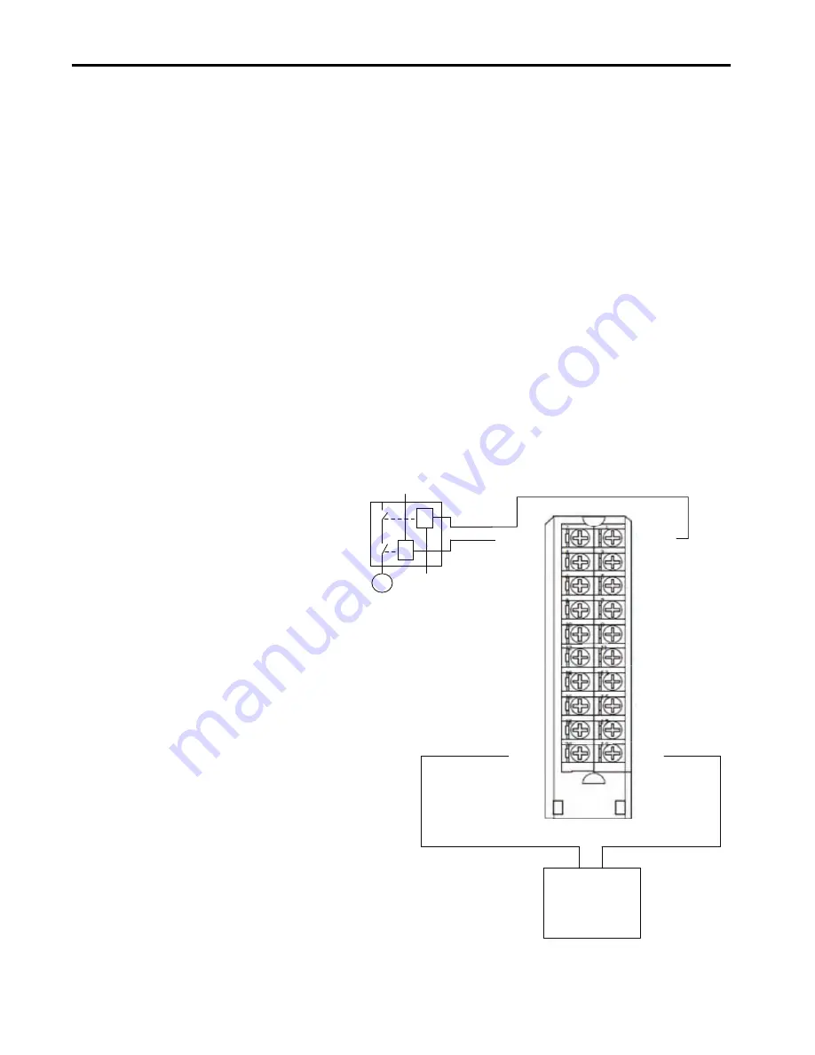
DC(+)
DC(-)
DC(+)
DC(-)
OUT0-P
OUT1-P
OUT4-P
OUT3-P
OUT2-P
OUT5-P
OUT6-P
OUT7-P
OUT0-M
OUT1-M
OUT2-M
OUT3-M
OUT4-M
OUT5-M
OUT6-M
OUT7-M
+ -
Actuator DC Power
In this wiring configuration, you must connect the
DC+ terminal to
an SELV/PELV-listed
power supply.
The DC+ and DC- on the actuator must be connected to the same
power supply as the DC+ and DC- on the module.
24V DC
SELV/PELV-listed power
supply
DC –
DC +
Channel Connections
This wiring example shows connections to the P-M pair for Safety
Output 0. You are not limited to using channel 0 in this mode. You can
use all channel pairs as determined by your application.
We
strongly recommend
that, if you have a direct connection
between the safety output module and an input module and those
modules are powered by separate power supplies, you connect the DC-
terminals together. This practice helps to eliminate grounding float
from disrupting diagnostics.
Connection Pairs
The terminals for each channel function as a Bipolar connection pair
when you use a 1756-OBV8S module in Bipolar switching mode. For
example, the Safety Output 0 P (Sourcing) terminal and
Safety Output 0 M (Sinking) terminal are a Bipolar connection pair.
That is, they are a P-M pair.
When the module is in Bipolar switching mode, you must connect the
device to both terminals.
K
K
M
Summary of Contents for 1756 Series
Page 135: ......