background image

Dealer/Distributor

DJ-195

Service Manual

ALINCO, INC.

Head Office : “TWIN 21” MID Tower Building 25F

1-61, 2-Chome, Shiromi, Chuo-ku, Osaka 540-8580 Japan
Phone: 06-6946-8150 Fax: 06-6946-8175 Telex: 63086
E-mail: [email protected]

U.S.A. : 438 Amapola Ave., Suite 130, Torrance, CA 90501-6201, U.S.A.

Phone: 310-618-8616 Fax: 310-618-8758
http://www.alinco.com/

Germany : Eschborner Landstrasse 55, 60489 Frankfurt am Main, Germany

Phone: 069-786018 Fax: 069-789-60766

Copyright 1999 Alinco, lnc. Osaka Japan

Printed in Japan

PM0058

Summary of Contents for DJ-195

Page 1: ...M5222FP 600C XA0385 10 4 TK14521MTL XA0515 11 5 M64082AGP XA0543 12 6 NJM2904V TE1 XA0573 12 7 NJM2902V TE1 XA0596 12 8 S 81250SG QD T1 XA0619 13 9 S 80845ALMP EA9 T2 XA0620 13 10 Transistor Diode and LED Ontline Drawings 14 11 LCD Connection EL0044 14 EXPLODED VIEW 1 Front View 15 2 Rear View 16 PARTS LIST MAIN Unit 17 19 Mechanical Parts 20 Packing Parts 20 ADJUSTMENT 1 Required Test Equipment 2...

Page 2: ......

Page 3: ...rature range 10 60 C 14 140 F Dimensions 56 W 124 H 40 D mm with EBP 48N Projections not included 2 2 W 4 88 H 1 57 D inches with EBP 48N Weight Approx 375g 13 2oz with EBP 48N DTMF 16 Buttons Keypad Sub audible Tone CTCSS encoder decoder installed 39tones Sub audible Tone DCS encoder decoder installed 104codes 2 TRANSMITTER Output power Approx 5W EBP 48N installed Approx 5W 13 8V DC Approx 0 8W L...

Page 4: ... cies The first IF amplifier Q10 then amplifies the signal of the selected fre quency 3 Demodulator Circuit After the signal is amplified by the first IF amplifier Q10 it is input to pin 16 of the demodulator IC IC5 The second local signal of 21 25MHz shared with PLL IC reference oscillation which is oscillated by the internal oscillation cir cuit in IC1 and crystal X1 is input through pin 1 of IC...

Page 5: ...inal amplifier Q2 The signal is then amplified by the final amplifier Q2 and led to the antenna switch D1 and low pass filter L5 L4 L3 L2 C16 C15 C14 and C13 where un wanted high harmonic waves are reduced as needed and the resulting signal is supplied to the antenna 3 APC Circuit Part of the transmission power from the low pass filter is detected by D6 con verted to DC and then amplified by a dif...

Page 6: ...y and 1 3 the bias at the frame frequency is 112 5Hz 2 Display Lamp Circuit When the LAMP key is pressed H is output form pin 50 of CPU IC9 to the bases of Q12 Q12 then turn ON and the LEDs D12 and D17 light 3 Reset and Backup When the power form the DC jack or external battery increases from Circuits 0 V to 2 5 or more H level reset signal is output form the reset IC IC11 to pin 33 of the CPU IC9...

Page 7: ...only 8 CTCSS DCS Decoder The voice band of the AF output signal from pin 10 of IC5 is cut by sharp active filter IC8 VCVS and amplified then led to pin 4 of CPU The input signal is compared with the programmed tone frequency code in the CPU The squelch will open when they match 9 Clock Shift In the unlikely event that CPU clock noise is present on a particular operating frequency programmed into t...

Page 8: ... RTX I Pulse UART data reception output 21 P43 TOUT BEEP I O Pulse Activ low Beep tone Band plan 3 when PSW is on 22 P42I NT2 RE2 I Avtiv low 23 P41 INT1 RE1 I Avtiv low Rotary encoder input 24 P40 SD O Avtiv low Signal detection output 25 P77 PTT I Activ high PTT input 26 P76 SDT I Activ high Trunking signal detection input 27 P75 P5C O Activ low PLL power ON OFF output 28 P74 T5C O Activ low TX ...

Page 9: ...17 O 72 SEG16 S16 O 73 SEG15 S15 O 74 SEG14 S14 O 75 SEG13 S13 O 76 SEG12 S12 O 77 SEG11 S11 O 78 SEG10 S10 O 79 SEG9 S9 O 80 SEG8 S8 O 81 SEG7 S7 O 82 SEG6 S6 O 83 SEG5 S5 O 84 SEG4 S4 O 85 SEG3 S3 O 86 SEG2 S2 O 87 SEG1 S1 O 88 SEG0 S0 O LCD segment signal 89 Vcc VDD CPU power terminal 90 Vref Vref AD converter power supply 91 Avss Avss AD converter GND 92 COM3 COM3 O LCD COM3 output 93 COM2 COM...

Page 10: ...9 SEMICONDUCTOR DATA 1 NMJ2070M T1 XA210 Low Voltage Power Amplifier Equivalent Circuit 2 AT24C16N 10SI 2 7TER XA0368 16K bits CMOS Serial EEPROM ...

Page 11: ...10 3 M5222FP 600C XA0385 Electronic Volume ...

Page 12: ...11 4 TK14521MTL XA0515 IF System ...

Page 13: ...12 5 M64082AGP XA0543 6 NJM2904V TE1 XA0573 Dual Single Supply Operational Amplifier 7 NJM2902V TE1 XA0596 Quad Single Supply Operational Amplifier ...

Page 14: ...13 8 S 81250SG QD T1 XA0619 Top View 9 S 80845ALMP EA9 T2 XA0620 Voltage Regulator ...

Page 15: ...TE85L XE0040 SML 310MTT86 XL0036 BRPG1201W TR XL0028 2SC4081 T106R XT0095 2SB766A TX XT0170 2SC4808 TX AR XT0171 2SA1036K T146Q XT110 2SD2216R TX XT0135 2SC2915 XT0178 2SC4618 XT0172 UN9216 R TX XU0099 XP1114 TX XU0161 XP1501 TX XU0172 RN2107 TE85L XU0192 RN1107 TE85L XU0193 RN1104 TE85L XU0195 RN2111 TE85L XU0194 11 LCD Connection EL0044 SEG0 SEG1 SEG2 SEG3 SEG4 SEG5 SEG6 SEG7 SEG8 SEG9 SEG10 SEG...

Page 16: ...15 EXPLODED VIEW 1 Front View www ALIMCO ru ...

Page 17: ...16 2 Rear View ...

Page 18: ...Chip C C1608CH1H100JT AS C79 CU0108 Chip C LMK212BJ105KG C80 CU3035 Chip C C1608JB1H102KT AS C81 CU3016 Chip C C1608CH1H270JT AS C82 CU3035 Chip C C1608JB1H102KT AS C83 CU3111 Chip C C1608JB1C104KT N C84 CU3035 Chip C C1608JB1H102KT AS C85 CU3016 Chip C C1608CH1H270JT AS C86 CU3035 Chip C C1608JB1H102KT AS C87 CE0392 Electrolytic C 6MV47UW C88 CU3035 Chip C C1608JB1H102KT AS C89 CS0405 Chip Tantal...

Page 19: ...1 Q4 XT0171 Transistor 2SC4808 TX AR Q5 XT0171 Transistor 2SC4808 TX AR Q6 XU0172 Transistor XP1501 TX Q7 XT0135 Transistor 2SD2216R TX Q8 XT0170 Transistor 2SB766A TX Q9 XE0040 FET 2SK882 GR TE85L Q10 XT0172 Transistor 2SC4618 Q11 XE0040 FET 2SK882 GR TE85L Q12 XU0193 Transistor RN1107 TE85L Q13 XT0178 Transistor 2SC4915 O TE85L Q14 XT0170 Transistor 2SB766A TX Q15 XU0193 Transistor RN1107 TE85L ...

Page 20: ... MCR03EZHJ100 R134 RK3058 Chip R MCR03EZHJ473 R135 RK3074 Chip R MCR03EZHJ105 R136 RK3050 Chip R MCR03EZHJ103 R137 RK3062 Chip R MCR03EZHJ104 R138 RK3069 Chip R MCR03EZHJ394 R139 RK3038 Chip R MCR03EZHJ102 R140 RK3065 Chip R MCR03EZHJ184 R141 RK3061 Chip R MCR03EZHJ823 R142 RK3058 Chip R MCR03EZHJ473 R143 RK3050 Chip R MCR03EZHJ103 R144 RK3062 Chip R MCR03EZHJ104 R145 RK3062 Chip R MCR03EZHJ104 R1...

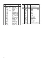
Page 21: ...E SHEET 195 TS0142 VCO case XH655 TW0020 W PROOF A XH720 UE0029A ANT CONNECT DJ460 UR0019 Dial RH70N00E20 RY 6320 YX0024 LCD TAPE DJ195 EA57 Antenna T E EAH EA58 Antenna TFH TLH PR0309 CE label E EAH EBP 48N EBP 48N HK0465 Pacage HM0189 Carton 10 HU0150 Inner C HU0151 Inner 5 BH0011 Belt clip BB0009Y Strap HP0003 Protection Bag 5 75 110 PR0237 FCC label DS0388A Spec sheet E EAH TFH TLH DS0411 Spec...

Page 22: ...mΦ 5 SSG Output frequency 200MHz or more Output level 20dBu 0 1uV 120dBu 1V Modulation FM 6 Spectrum Analyzer Measuring range Up to 2GHz or more 7 Power meter Measurable frequency Up to 200MHz Impedance 50Ω unbalanced Measuring range 0 1W 10W 8 Audio volmeter Measurable frequency Up to 100kHz Sensitivity 1mV to 10V 9 Audio generator Output frequency 67Hz to 10kHz Output impedance 600Ω unbalanced 1...

Page 23: ...ard modulation 1kHz 3 5kHz DEV Reference sensitivity 12dB SINAD Specified audio output leve 200mW at 8Ω Standard audio output level 50mW at 8Ω Use an RF cable 3D2W 1m for test equipment Attach a fuse to the RF test equipment All SSG outputs are indicated by EMF Supply voltage for the transceiver 13 8VDC ...

Page 24: ...lue 1MHz listed in the table below To enter the adjustment mode set key lock and input 490217 Decimal point at 100MHz and 10MHz appears in LCD To release the mode set key lock and input 490217 Channel frequencies used in the adjustment mode Channel Channel function Frequency 1 2 3 4 5 6 7 8 9 10 11 12 13 14 15 16 17 Reference frequency adjustment High power adjustment Low power adjustment Minimum ...

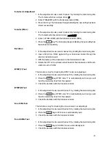
Page 25: ...3 While watching the reading of the TX power meter set the output power to the value closest to 0 8 W by rotating the main tuning dial 4 When the key is released the output power at that time will be stored as the low power setting Minimum Frequency Sensitivity Adjustment See Note on Adjusting the Sensitivity later in this section 1 In the adjustment mode select channel 4 by rotating the main tuni...

Page 26: ...ransceiver until the de viation is set to 4 5KHz DTMF 1 Test This function is only for checking the DTMF code not adjusting it 1 In the adjustment mode select channel 10 by rotating the main tuning dial 2 Press the key DTMF code 1 is automatically sent and you will hear the monitoring tone from the speaker 3 Check the deviation with the transceiver tester DTMF D Test 1 In the adjustment mode selec...

Page 27: ...1 In the adjustment mode select channel 17 by rotating the main tuning dial The transceiver automatically repeaters transmission for a minute and re ception for another minute Note on Adjusting Sensitivity Sensitivity is adjusted by applying the optimum voltage from the CPU to the varicap of the tuning circuit 1 Program any frequency within 145MHz 1MHz on memory channel 5 2 To enter the adjustment...

Page 28: ......

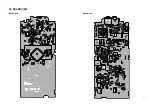
Page 29: ...27 PC BOARD VIEW MAIN SIDE A MAIN Side B ...

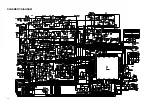
Page 30: ...28 SCHEMATIC DIAGRAM ...

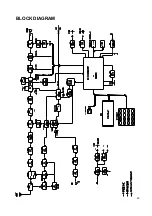
Page 31: ...29 BLOCK DIAGRAM www ALIMCO ru ...

Page 32: ......

Page 33: ......

Page 34: ...6 6946 8150 Fax 06 6946 8175 Telex 63086 E mail 101243 1446 compuserve com U S A 438 Amapola Ave Suite 130 Torrance CA 90501 6201 U S A Phone 310 618 8616 Fax 310 618 8758 http www alinco com Germany Eschborner Landstrasse 55 60489 Frankfurt am Main Germany Phone 069 786018 Fax 069 789 60766 Copyright 1999 Alinco lnc Osaka Japan Printed in Japan PM0058 ...

Reviews: