24
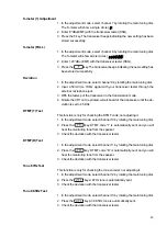
Reference Frequency Adjustment
1. In the adjustment mode, select channel 1 by rotating the main tuning dial.
2. Press the
key to start transmission.
3. Rotate TC1 on the Main board until the value on the frequency counter
matches the one displayed on the LCD.
4. On 145.05MHz measure TP1 near the VCO and to obtain 1.2V+0.1V
( If the frequency display is flashing, the PLL is unlocked. )
High Power Adjustment
1. In the adjustment mode, select channel 2 by rotating the main tuning dial.
2. Hold down the
key to start transmission.
3. While watching the reading of the TX power meter, set the output power to
the value closest to 5 W by rotating the main tuning dial.
4. When the
key is released, the output power at that time will be
stored as the high power setting.
Low Power Adjustment
1. In the adjustment mode, select channel 3 by rotating the main tuning dial.
2. Hold down the
key to start transmission.
3. While watching the reading of the TX power meter, set the output power to
the value closest to 0.8 W by rotating the main tuning dial.
4. When the
key is released, the output power at that time will be
stored as the low power setting.
Minimum Frequency Sensitivity Adjustment
See “Note on Adjusting the Sensitivity” later in this section.
1. In the adjustment mode, select channel 4 by rotating the main tuning dial.
2. Set the minimum frequency sensitivity rotating the main tuning dial, while F
appears after the
key is pressed.
Medium Frequency Sensitivity Adjustment
See “Note on Adjusting the Sensitivity” later in this section.
1. In the adjustment mode, select channel 5 by rotating the main tuning dial.
2. Set the medium frequency sensitivity rotating the main tuning dial, while F
appears after the
key is pressed.
Maximum Frequency Sensitivity Adjustment
See “Note on Adjusting the Sensitivity” later in this section.
1. In the adjustment mode, select channel 6 by rotating the main tuning dial.
2. Set the maximum frequency sensitivity rotating the main tuning dial, while F
appears after the
key pressed.
Summary of Contents for DJ-195
Page 2: ......
Page 11: ...10 3 M5222FP 600C XA0385 Electronic Volume ...
Page 12: ...11 4 TK14521MTL XA0515 IF System ...
Page 14: ...13 8 S 81250SG QD T1 XA0619 Top View 9 S 80845ALMP EA9 T2 XA0620 Voltage Regulator ...
Page 16: ...15 EXPLODED VIEW 1 Front View www ALIMCO ru ...
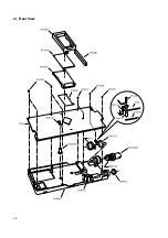
Page 17: ...16 2 Rear View ...
Page 28: ......
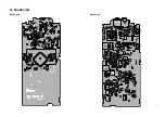
Page 29: ...27 PC BOARD VIEW MAIN SIDE A MAIN Side B ...
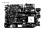
Page 30: ...28 SCHEMATIC DIAGRAM ...
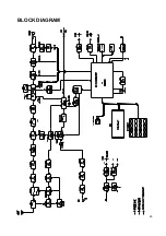
Page 31: ...29 BLOCK DIAGRAM www ALIMCO ru ...
Page 32: ......
Page 33: ......


