


2
www.observint.com
7.
Connect the other end of the power extension cable to a 12 Vdc power source. Observe the
connector polarity of the cable shown in the photo on page 1 of this guide.
•
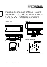
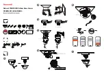
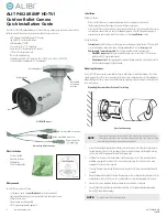
Mounting the camera with a junction box
The ALI-AJ6 junction box is shown below. It can be attached to a wall or ceiling. Video and power
extension cables can be routed in through the opening in the back of the box or through the conduit
coupling, and attached to the camera drop cables inside the enclosure.
Front
Front
plate
Box
Conduit
coupling/
cable
channel
Back
“UP”
label
Holes for
mounting
screws (3)
Holes for
mounting
base
screws (6)
To use the junction box:
1.
Remove the ALI-AJ6 front plate from the box by removing the three screws (see above).
2.
Attach the front plate to the camera mounting base using three screws. If the box will be wall
attached to a wall, ensure that the “
UP
” label on the mounting plate is at the top of the camera, and
the cable channel in the camera mounting base is toward the bottom of the camera.
3.
Using the ALI-AJ6 box as a guide, mark and then drill three holes for the screws that will attach the
box to the wall or ceiling. If the extension cables will be routed into the box through the mounting
surface, also drill a hole for the extension cables.
4.
Attach the box to a wall or ceiling with three screws. Ensure that the wall or ceiling will support at
least three times the weight of the camera with the junction box.
5.
Route the video and power extension cables into the box.
6.
Attach the video and power extension cable to the camera drop cables. Observe the polarity of the
power cable connector as shown on page 1 of this guide.
7.
Attach the ALI-AJ6 front plate (with the camera) to the box.
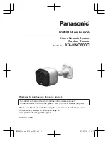
Camera adjustments
1.
Apply power to the camera.
2.
Verify that video from the camera can be seen on the monitor.
3.
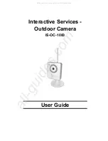
While observing video from the camera, loosen the mounting bracket pan lock nut, point the
camera at your surveillance target, and then tighten the pan lock nut to hold the camera in position.
0° ~ 180°
0° ~ 360°
0° ~ 360°
Rotation: Use for
horizon line adjustment
Pan lock nut: loosen for pan,
tilt and rotation adjustments
Tilt: Use for
elevation
adjustment
Mounting bracket adjustment
Step 1. Open the OSD menu
The On Screen Display (OSD) provides configuration options for refining the performance of the camera.
It also can be used to block sensitive portions in the field of view (Privacy). You can open the OSD menu
system from either the Recorder Live View display or through remote login to the ALIBI recorder.
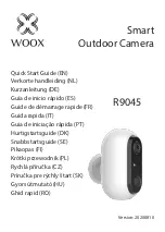
Opening the OSD Menu through the recorder
To open the OSD menu on the recorder monitor:
1.
Open the recorder Live View screen, and then click inside the screen where the PTZ camera video
image is displayed. See below.
2.
Click the
PTZ Control
icon in the Quick Setting Toolbar. The PTZ camera Live View window will
expand to full screen and the pop-up window shown below will open.
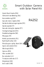
Menu
icon
3.
In the
PTZ Control
panel pop-up window, click the
Menu
icon on the
Configuration
line.
4.
Drag the PTZ Control window to a position where it doesn’t cover the OSD menu (such as the left
side).
NOTE
The PTZ Control window direction buttons and the
Iris +
and
Iris
-
keys are used to navigate the
OSD menu and set configuration options in the camera. See “OSD Definitions: On-screen Display
(OSD) menus” on page 5.
Opening the OSD Menu through remote login to the recorder
To open the OSD menu during a remote login to the recorder:
1.
After logging into the recorder, open the camera in a single Live View window.
© 2018 Observint Technologies. All rights reserved.