8
6.2 THERMO VALVE (Fig. 7, Item 13)
Installation of a thermo valve is MANDATORY in a closed circuit. This specially refers to a closed circuit,
when the radiators are submerged and where, in the event that pump operation is stopped for any reason, water
temperature in the boiler rapidly increases and overheating occurs very quickly.
In central heating open circuits, installation of thermo valves is not mandatory.
You can connect the thermo valve to the upper or lower R1/2" connection, depending on the available space,
only you must observe the direction of water inlet and outlet, which is clearly marked on the valve body.
Place the thermo valves safety pipe in the opening of the thermo valve connection (Fig. 4, Item 5 and Fig. 7,
Item 18). Seal it with hemp or other sealing material by tightening.
Fig. 7 shows the thermo valve installation diagram.
6.3 SAFETY VALVE (Fig. 7 and 8, Item 5 and Fig. 4, Item 6)
An R1/2" connection (Fig. 4, Item 6) is welded at the back of the boiler, under the cooktop frame, on which a
safety valve MUST be fitted. The safety valve should be 2.5 to 3 bars. You can fit it directly on the connection
or at a distance from the connection of at least 1 m, provided that there is no block valve between the boiler and
the safety valve.
In general, safety valve is not fitted in open circuits, but we advise you to fit it nonetheless, as another safety
precaution for the boiler and the system (in case of emergency).
NOTE:
If the safety valve is not fitted as described above, the warranty will not be valid.
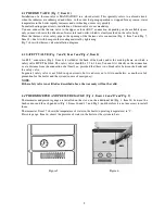
6.4 THERMOMETER AND PRESSURE GAUGE (Fig. 1, Items 16 and 17 and Fig. 5)
Thermometer and pressure gauge are installed on the stove, on the additional lid (Fig. 1, Item 24) between the
firebox door and the ash pan door (Fig. 1, Items 16 and 17, and Fig. 5) and therefore it is not necessary to install
them.
Thermometer, Item 17, shows the temperature of water in the boiler (operating temperature) in ºC.
Pressure gauge, Item 16, shows the pressure of water in the boiler or the system in bars.
Figure
5
Figure 6

