7
6. INSTALLING THE STOVE IN THE WATER HEATING SYSTEM
The stove should be installed by a professional, in accordance with appropriate design.
The stove is intended for local and central heating.
The stove can be installed in closed or open heating circuit. Conform to the standards: JUS M.E7.201 and JUS
M.E7.202. Closed and open circuit diagrams are shown on Fig. 7 and Fig. 8.
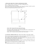
The back of the boiler and connections are shown on Fig. 4 where:
Figure 4
-
Item 1 is an R1" connection with an outer thread for the flow pipe,
-
Item 2 is an R 1" connection with an outer thread for the return pipe,
-
Items 3 and 4 are R1/2" connections (2 pcs) with an outer thread. These are cooling pipe outlets and
any of which can be used as an inlet or outlet,
-
Item 5 is an R1/2" connection with an inner thread for installation of the thermo valve safety pipe,
-
Item 6 is an R1/2" connection with an inner thread for safety valve installation.
6.1 FLOW PIPE AND RETURN PIPE (Fig. 4, Items 1 and 2 and Fig. 7 and 8, Items 3 and 10)
The size of the flow pipe and return pipe outlets is 1" and may not be reduced or tapered before the first branch.
Use 1" steel pipe or copper pipe of outer diameter Ø 28 mm (or larger diameter).
While installing the system, absolutely make sure that pipe slopes are 0.5% (5 mm of pipe length) and that the
air is released from the system (from the boiler, pipes, radiators).
You can install a combination temperature and pressure gauge on the flow pipe, although both thermometer and
pressure gauge are installed at the front of the stove.
On the return pipe, install a by-pass line with a pump, expansion vessel and a spigot for filling up and emptying
the system. When you install the pump, take note of the pump’s direction.
Note:
Only install the by-pass line if there are conditions for gravity heating.

