Alfa IN PEGAS 250 MIG SYN Instruction Manual Download Page 11

11/23 

ALFA IN a.s. © 


www.alfain.eu 

3.  If there is a suitable groove on the roll, rotate the roll and place it back on 

the shaft and secure it by screwing the element 

E5


ADJUSTING THE MACHINE FOR WELDING OF ALUMINIUM 

For  feeding  the  AL  wire  it  is  necessary  to  use  roll  with  the  “U”  profile  -  see 
paragraph OVERVIEW ROLLS WIRE FEED. To prevent problems with feeding 
use wires with diameter. 1.0 mm of AIMg3 or AlMg. Wire of alloy Al99, 5 or AlSi5 
are too soft and easily will cause problems with movement.


For the aluminum welding it is also necessary to provide the torch tefl. liner and 
special current nipple. We do not recommend you to use the torch longer than 3 
m. Great attention must be paid to adjust the contact power of rolls – it must not 
be too high, otherwise there is a deformation of the wire.


As a protective atmosphere is necessary to use argon.  
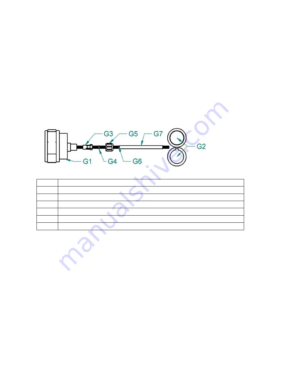
 

Picture

 4

 – Customization of the feed for the aluminium wire 

G1 

EURO connector  

G2 

Rolls 

G3 

Liner terminal for 4,0mm, 4,7mm outer diameter 

G4 

O-ring 3,5 x1, 5mm to prevent escape of gas 

G5 

Nut  

G6 

Liner tefl. 

G7 

Sustain pipe for teflon and plastic liner 

INSERTING THE WIRE 

1.  Open the side cover of the wire feeder space 
2.  Put the wire spool on the wire spool holder 

D1

 and fix it with the fixing nut 

D2

. If a spool (size of 15 or 18 kg) is used, put on each side of the spool 

adapter 

D3

. The hole in the back of the adapter must fit into the pin on the 

wire spool holder! 

3.  Cut off the curved or damaged end of welding wire and lead it through the 

inlet liner 

E3,

 and the roll into the liner inside the EURO torch connector 

(about 5 cm). Make sure, that you use the suitable groove. 

4.  Put the pressure arm 

E2

 down in that way, that the teeth or the gear fit and 

fix it by setting the lever 

E1

 into vertical position. 

5.  Adjust  the  pressure  nut  that  way  that  it  provides  constant  movement  of 

wire but it does not deform wire. The adjusting screw is located under the 
plastic screw 

E1

Summary of Contents for PEGAS 250 MIG SYN

Page 1: ...ALFA IN a s www alfain eu PEGAS 250 320 MIG SYN manual EN 05 WELDING MACHINES PEGAS 250 MIG SYN PEGAS 320 MIG SYN INSTRUCTION MANUAL...

Page 2: ...UTIONS 4 3 OPERATING CONDITIONS 5 4 TECHNICAL DATA 6 5 ACCESSORIES 7 6 DESCRIPTION OF THE APPLIANCE 8 7 BASIC SETTINGS 14 8 MIG MAG WELDING SYNERGY 17 9 MIG MAG WELDING MANUAL 18 10 MMA WELDING COATED...

Page 3: ...nections of structural steels With welding machine PEGAS 250 320 MIG SYN it is possible to weld different types of connections blunt single sided double sided fillet lap etc using wire diameter from 0...

Page 4: ...resh air because during welding harmful fumes arise 5 In tanks of gas oil fuel etc even empty ones do not make welding because there is a chance of explosion 6 In areas with chance of explosion specia...

Page 5: ...removal of the plug fuse replacement should be performed by an authorized person 8 With competent mains voltage and input must match the plug 9 Do not use the machine for other purposes such as defro...

Page 6: ...rent DZ x I2 A 60 250 50 250 25 315 20 300 Protection IP 23S Standards EN 60974 1 EN 60974 10 cl A Dimensions w x d x h mm 240 x 640 x 438 Weight kg 26 6 Wire feed speed m min 1 0 15 1 0 15 Spool diam...

Page 7: ...T Designation Description VM0321 3 Hose for gas connection PEGAS 3m 012 0252 Welding torch MB 24KD 4 m GRIP VM0023 Welding cables PEGAS 2x 3m 35 50 NOTICE If you decide to use a different torch than t...

Page 8: ...6 A5 Current encoder A6 Control light Material thickness mm A7 Control light Wire speed m min A8 Button for selecting the parameters to be displayed A9 Control light Current A A10 Left display A11 Rig...

Page 9: ...e arm E2 Pressure arm E3 Inlet liner E4 EURO connector E5 Roll CHOOSING THE FEEDING ROLL In all machines ALFA IN MIG MAG rolls with two grooves are used These grooves are intended for two different wi...

Page 10: ...5438 Flux core 0 8 1 0 2318 5439 1 0 1 2 2319 5440 1 2 1 4 2320 5441 ADJUSTING THE MACHINE FOR ANOTHER WIRE DIAMETER In all machines ALFA IN MIG MAG are used rolls with two grooves These grooves are...

Page 11: ...Customization of the feed for the aluminium wire G1 EURO connector G2 Rolls G3 Liner terminal for 4 0mm 4 7mm outer diameter G4 O ring 3 5 x1 5mm to prevent escape of gas G5 Nut G6 Liner tefl G7 Susta...

Page 12: ...pressure force is too high it will lead to increased mechanical wear of bearings and it can damage the machine Before putting into operation clean the rolls from preservative oil INSERTING THE WIRE TO...

Page 13: ...ecuring of gas bottle Information can be obtained from a supplier of industrial gases 1 Fit the gas hose to the outlet on the back panel of the machine 2 Press button pic 1 A2 on the main panel If you...

Page 14: ...or SYN MIG MAG synergistic Confirm your choice by pressing the button A5 QUICK SETTING THE JOB MEMORY Works for three welding methods 1 Long press one of the buttons A4 1 2 3 4 5 6 to save set parame...

Page 15: ...nge the secondary parameters Secondary parameters for manual and synergistic methods are identical 1 Simultaneously pressing A19 and A5 encoder enters the menu for secondary parameters 2 A5 encoder se...

Page 16: ...atically locked when the torch trigger is pressed H5 When the LED is on it indicates UP DOWN and M button are functioning H6 Torch button UP H7 Torch button DOWN HOW TO SWITCH ON THE REMOTE CONTROL OF...

Page 17: ...3 s makes RESET default parameters will be restored 2 It will delete saved JOBs 8 MIG MAG WELDING SYNERGY 1 Choose SYN method see SETTING THE METHOD OF WELDING 2 Left display A10 shows SYN right disp...

Page 18: ...encored A16 9 MIG MAG WELDING MANUAL 1 Choose MAN method see SETTING THE METHOD OF WELDING 2 The left display A10 shows MAN 3 The left display A10 shows the wire feed speed the right display A11 show...

Page 19: ...elding current the right display A11 shows ELE 3 The welding current is set by the encoder A5 4 During welding the display shows measured values of welding current 5 After welding on the display will...

Page 20: ...pairs must know what to look at what to look for and what to do OPERATIONAL SAFETY INSPECTION OF THE MACHINE ACCORDING TO SN EN 60 974 4 Prescribed operations of tests procedures and required document...

Page 21: ...ate supply of a protective gas pores in the weld Poorly set the amount of supplied gas Set the correct amount as described in this instruction manual Reducing valve on the bottle is dirty Check and re...

Page 22: ...e date of sale to the end user 4 If warranty is being sought please contact your ALFA IN product supplier for the warranty repair procedure 5 ALFA IN warranty will not apply to 1 Equipment that has be...

Page 23: ...te material In accordance with European Council Directive 2002 96 EC on electrical and electronic equipment waste and its implementation in accordance with national law electric tools that have reache...

Reviews: