background image

Alesis QuadraVerb Service Manual------ 

16 

08/13/04 

10.0 Software History 


DATE VERSION 

COMMENTS 


1/15/89 

1.00 

1)  First production release 


1/23/89 

1.01 

1)  Added test routines for production testing, including RAM, ROM, LEDs, MIDI, and 

CLIP tests. 


2/22/89 

1.02 

1)  Fixed bug that caused a gated effect to be heard on graphic EQ and delay mode 

programs if the previously selected program was a gated program. 


2)  Fixed bug that caused a volume drop in the mid band EQ if the frequency was 

9874Hz, amp14.00 dB, and bandwidth of 2.55 octaves. 


3)  Default setting for direct signal level changed to 50 from 99. 


4)  Default setting for reverb level changed to 99 from 50. 


5)  Fixed bug that caused the bypass level of lezlie programs to be unpredictable.  Now, 

the bypass level will be the same as the lezlie level. 


6)  All 90 factory programs updated to newer versions. 


3/8/89 

1.03 

1)  Changed bypass level of direct signal so that the master effect level would be used 

to scale the bypass level if the current program did not have any direct signal in it. 


2)  Changed default mix settings of the last 10 programs (90-99) so that direct level is 

50 (instead of 99), delay is 50 (instead of 40), and reverb is 99 ( instead of 40). 


3)  All 90 factory programs updated to newer versions. 


11/30/89 

1.05 

1) Software version accommodates new hardware in which VCA after DAC is 

removed.  This means that the master effects level is controlled by scaling the 
amplitude of each effect in software, instead of changing the VCA level.  If this 
software is used with older hardware, the VCA will be left full open, so that the 
operation will be the same as with the newer hardware. 


2)  When changing programs with bypass on, the dry level will now change with each 

program to reflect the level of the dry signal in that program. 


3)  When a program is stored, the display now reads "PROGRAM STORED" instead 

of "PROGAM STORED". 


3/8/90 

1.07 

1)  The 11 band graphic EQ algorithm has been modified to decrease the noise present 

when one of the bands between 250Hz and 16KHz was set to a few dB of cut. 


2)  The duty cycle of the EQ cursor flashing has been changed to improve its visibility. 


8/10/90 

2.00 

1)  Quadraverb Plus first release.  Too many features to describe. 


Summary of Contents for QUADRAVERB

Page 1: ...Alesis QuadraVerb Service Manual i 08 13 04 Alesis QuadraVerb Service Manual Revision 1 00 6 28 94 ...

Page 2: ...ice or repairs done by you or with reference to the Manual shall be solely your responsibility and Alesis shall have no liability for any such repairs or service work All such service or repairs are performed at the sole risk of the person performing the service or repairs You agree that all such work will be performed in a competent professional and safe manner at all times and to indemnify and f...

Page 3: ...ger of explosion if battery is incorrectly replaced Replace only with the same type or equivalent type recommended by the equipment manufacturer Battery Manufacturer Tadiran Type TL 5101 Rating 3 6V REPAIR BY ANY PERSON OR ENTITY OTHER THAN AN AUTHORIZED ALESIS SERVICE CENTER WILL VOID THE ALESIS WARRANTY PROVISION OF THIS MANUAL DOES NOT AUTHORIZE THE RECIPIENT TO COMPETE WITH ANY ALESIS DISTRIBU...

Page 4: ...re not to allow liquids to spill or objects to fall into any openings of the product 6 Water or Moisture The product should not be used near any water or in moisture 7 Heat Do not place the product near heat sources such as stoves heat registers radiators or other heat producing equipment 8 Ventilation When installing the product make sure that the product has adequate ventilation Improperly venti...

Page 5: ... as capacitors that begin to leak excess current after a significant amount of time 5 Cable Checks Wiggling cables can reveal intermittent failures such as loose cables or poorly soldered headers Remember to check power supply cables as well 6 Flexing the PC Board Poor solder joints and broken traces can often be found by pressing the PC Board in various places 7 Tapping Componants Somtimes tappin...

Page 6: ...ed I O 5 4 4 Analog Input and the 8031 5 4 5 DASP 24 ASIC 5 5 0 Test Procedures 6 6 0 Adjustments 6 7 0 Updates and Revisions 6 7 1 D15 7 7 2 Header Capacitor 7 7 3 R66 7 7 4 SRAM Supply 7 7 5 Battery Ground 7 7 6 Cables 7 7 5 LCD Contrast 7 7 6 LCD Cable Header 7 7 7 Wet VCA Removal 7 7 8 DAC Adjustment Installation 8 7 9 Increasing Output Gain 8 7 10 QV I P Filter Kit Installation 8 8 0 Helpful ...

Page 7: ...well as effects such as chorus and flange that require real time manipulation of algorithms Please note that there are several different main PCB revisions so differences will be noticed from unit to unit Alesis QuadraVerb Service Manual 1 08 13 04 2 0 Power Supply The power supply begins with the 9 Volt A C adapter Input from J6 is R F filtered by C31 before on off switch S1 From there it is spli...

Page 8: ...ffered by U1 A C coupled C1 C2 and passed through a variable input level X10 gain stage The stereo signal is then sent to the outputs via the dry VCA U5 It is also summed to mono Via R17 R18 before being passed along to the anti aliasing filter discussed later and the LED control circuit The LED circuit consists of a rectifier U4 D2 a fairly standard comparator ladder U7 associated resistors and a...

Page 9: ...ry as well as facilitating easier servicing 3 2 Successive Approximation Successive approximation is a heuristic approach to the process of analog to digital conversion The idea is to divide the process into short manageable sections Each significant binary weight starting with the Most Significant Bit is taken in turn thus requiring only 16 comparisons to achieve a final value The process begins ...

Page 10: ...al Data and TXD Transmit Serial Data ports Front panel keypad decoding is handled through a combination of memory mapped I O see section 4 3 and the 8031 s built in I O ports 4 2 Reset The 8031 reset circuit is perhaps the single most important circuit in the QuadraVerb When this circuit is functioning incorrectly problems ranging from loss of battery backup to a complete lock up of the machine ca...

Page 11: ...s used to accomplish this We will examine the audio threshold input The principle will also apply to the piezo Z2 value input circuit The process begins with the 8031 temporarily turning on Q2 via mapped I O latch U29 After turning Q2 back off the 8031 begins counting While the 8031 is counting C56 charges through R51 This signal is compared to the incoming rectified analog signal from the LED con...

Page 12: ...al corrupt data etc Saving user data may also be accomplished after unit functionality is restored i e power supply or reset line is repaired and prior to further servicing and testing The unit should always be reinitialized power unit up while holding BYPASS and PROG buttons down after changing the EPROM SRAM or any part of the battery backup To perform the QuadraVerb s self diagnostics connect a...

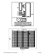
Page 13: ... which can cause data corruption Alesis QuadraVerb Service Manual 7 08 13 04 7 5 Battery Ground Check battery GND connection and resolder if necessary Cold solder joints can exist there resulting in memory loss and crashing Diagram 5 7 6 Cables Check all connector cables are firmly seated In some cases they can come 1 2 way off 7 5 LCD Contrast Check LCD contrast if contrast is too dark then short...

Page 14: ...discretion of the technician 7 10 QV I P Filter Kit Installation The following update enhances the input filter of the Quadraverb by increasing the number of filter poles from 4 to 6 This gives a corresponding increase in the filter rolloff rate and eliminates problems encountered when using the QV with high bandwidth samplers such as the Ensoniq ESQ 1 the Roland D 50 or the EMU Proteus Here is a ...

Page 15: ...emphasis will not be correct and the unit will sound shrill It is recommended but not absolutely necessary to install R20 200K R44 200K R45 1M and the 250K trimpot R43 When it comes time to adjust the DAC use a fast LEZLIE program and adjust the trimpot for minimum output noise with no input signal and maximum output level Replace the rest of the components per the above value change list To test ...

Page 16: ...Diagram 7 Alesis QuadraVerb Service Manual 10 08 13 04 ...

Page 17: ...Diagram 8 Diagram 9 Alesis QuadraVerb Service Manual 11 08 13 04 ...

Page 18: ...U21 pin 9 both during power up and down Troubleshoot if necessary Bad 80C31 Replace and re test Bad 24MHz Crystal Z1 Some crystals are shock sensitive Tapping on the crystal can sometimes reveal this Bad LCD Replace and re test Bad LCD cable Replace and re test No Memory Bad battery Replace and re test Check R61 per section 2 1 Be aware that most battery failures are caused by a component failure ...

Page 19: ...pe probe so explore The Curtiss VCAs U5 and possibly U6 are current driven devices so don t expect to see any signals from these chips on a scope Be on the watch for user error i e if a user complains that it won t load from a DataDisk check to be sure that SYSEX ENABLE is turned on Remember to install ALL of the latest revisions before returning the unit This can help prevent many unhappy returns...

Page 20: ...9 0 Schematics Alesis QuadraVerb Service Manual 14 08 13 04 ...

Page 21: ...Alesis QuadraVerb Service Manual 15 08 13 04 ...

Page 22: ...d not have any direct signal in it 2 Changed default mix settings of the last 10 programs 90 99 so that direct level is 50 instead of 99 delay is 50 instead of 40 and reverb is 99 instead of 40 3 All 90 factory programs updated to newer versions 11 30 89 1 05 1 Software version accommodates new hardware in which VCA after DAC is removed This means that the master effects level is controlled by sca...

Page 23: ...n Sample configuration the EQ and BYPASS buttons could not be used to enter a new program number while holding the PROG button This is now fixed 3 When selecting a program that was set to the Sample configuration while audio was present would occasionally result in noise at the audio output until a sample was recorded This is now fixed 3 10 92 2 03 1 If a MIDI controller was routed to modulate the...

Page 24: ...ter value in the following format Data B7 B6 B5 B4 B3 B2 B1 B0 MSB A7 A6 A5 A4 A3 A2 A1 A0 LSB Sent 0 A7 A6 A5 A4 A3 A2 A1 value1 0 A0 B7 B6 B5 B4 B3 B2 value2 0 B1 B0 0 0 0 0 0 value3 All parameters to be edited must be sent in this format 12 MIDI bytes regardless of the number of bits required to transmit the value of the parameter When the QuadraVerb receives this message it will edit the speci...

Page 25: ...B0 2 C7 C6 C5 C4 C3 C2 C1 C0 3 D7 D6 D5 D4 D3 D2 D1 D0 4 E7 E6 E5 E4 E3 E2 E1 E0 5 F7 F6 F5 F4 F3 F2 F1 F0 6 G7 G6 G5 G4 G3 G2 G1 G0 TRANSMITTED AS 0 0 A7 A6 A5 A4 A3 A2 A1 1 0 A0 B7 B6 B5 B4 B3 B2 2 0 B1 B0 C7 C6 C5 C4 C3 3 0 C2 C1 C0 D7 D6 D5 D4 4 0 D3 D2 D1 D0 E7 E6 E5 5 0 E4 E3 E2 E1 E0 F7 F6 6 0 F5 F4 F3 F2 F1 F0 G7 7 0 G6 G5 G4 G3 G2 G1 G0 There are 147 bytes sent for a single data dump whic...

Page 26: ...hase etc In conditions where a page relates to different parameters depending on the mode of the effect the parameters are listed in tables under each mode All parameters are offset binary values This means that a signed parameter with a range of 99 to 99 in the display is actually stored as 0 for 99 99 for 0 and 198 for 99 REVERB FUNCTION 1 CONFIGURATION 0 5 6 page 0 type 0 PLATE 1 1 ROOM 1 2 CHA...

Page 27: ...1 198 PRE MIX 1 198 PRE MIX 1 198 PRE MIX 1 198 PRE MIX 1 198 PRE MIX 4 0 99 DECAY 0 99 DECAY 0 99 DECAY 0 99 DECAY 0 99 REV TIME 5 0 8 DIFFUSION 0 8 DIFFUSION 0 8 DIFFUSION 0 8 DIFFUSION 0 8 DIFFUSION 6 0 8 DENSITY 0 8 DENSITY 0 8 DENSITY 0 60 LOW DEC 0 8 DENSITY 7 0 60 LOW DEC 0 60 LOW DEC 0 60 LOW DEC 0 60 HIGH DEC 0 60 LOW DEC 8 0 60 HIGH DEC 0 60 HIGH DEC 0 60 HIGH DEC 0 1 GATE ON 0 60 HIGH D...

Page 28: ...50 L DELAY 1 750 DELAY 3 0 99 FEEDB 0 99 L FEEDB 0 99 FEEDB 4 1 750 R DELAY 5 0 99 R FEEDB CONFIGURATION 3 page 0 type 0 MONO 1 STEREO 2 PING PONG 3 MULTI TAP 1 0 1 INPUT 0 1 INPUT 0 1 INPUT 0 1 INPUT 2 0 198 IN MIX 0 198 IN MIX 0 198 IN MIX 0 198 IN MIX 3 1 1500 DELAY 1 750 L DELAY 1 750 DELAY 0 7 TAP NUMBER 4 0 99 FEEDB 0 99 L FEEDB 0 99 FEEDB 1 1493 TAP DELAY 5 1 750 R DELAY 0 99 TAP VOLUME 6 0...

Page 29: ...127 MIDI HI LIMIT PITCH FUNCTION 3 CONFIGURATION 0 3 page 0 type 0 M CHORUS 1 S CHORUS 2 M FLANGE 3 S FLANGE 4 DETUNE 5 PHASER 1 0 1 INPUT 0 1 INPUT 0 1 INPUT 0 1 INPUT 0 1 INPUT 0 1 INPUT 2 0 1 WAVE 0 1 WAVE 0 99 SPEED 0 99 SPEED 0 198 TUNE 0 99 SPEED 3 0 99 SPEED 0 99 SPEED 0 99 DEPTH 0 99 DEPTH 0 99 DEPTH 4 0 99 DEPTH 0 99 DEPTH 0 99 FBACK 0 99 FBACK 5 0 99 FBACK 0 99 FBACK 0 1 TRIGGER 0 1 TRIG...

Page 30: ...5 0 60 RESONATOR 4 TUNE 6 0 60 RESONATOR 5 TUNE EQ FUNCTION 4 CONFIGURATION 0 4 page 0 20 999 LOW FREQUENCY 1 0 560 LOW BOOST CUT 2 200 9999 MID FREQUENCY 3 20 255 MID BANDWIDTH 4 0 560 MID BOOST CUT 5 2000 18000 HIGH FREQUENCY 6 0 560 HIGH BOOST CUT CONFIGURATION 1 page 0 0 26 HIGH ROTOR LEVEL CONFIGURATION 2 page 0 0 28 16Hz 1 0 28 32Hz 2 0 28 62Hz 3 0 28 126Hz 4 0 28 250Hz 5 0 28 500Hz 6 0 28 1...

Page 31: ...560 HIGH MID BOOST CUT 11 2000 18000 HIGH FREQUENCY 12 0 560 HIGH BOOST CUT CONFIGURATION 5 6 7 Not used CONFIGURATION FUNCTION 7 page 0 0 4 CONFIGURATION 0 EQ PCH DL REVERB 1 LESLIE DL REVERB 2 GRAPHIC EQ DELAY 3 5BAND EQ PCH DLY 4 3 BAND EQ REVERB 5 RING DL REVERB 6 RESONATOR DL REVERB 7 SAMPLING MIX FUNCTION 8 CONFIGURATION 0 page 0 type 0 PRE EQ 1 POST EQ 1 0 99 DIRECT 0 99 MAST FX 2 0 99 MAST...

Page 32: ...FX 2 0 99 MAST FX 0 99 EQ 3 0 99 PITCH 0 99 PITCH 4 0 99 DELAY 0 99 DELAY CONFIGURATION 4 page 0 type 0 PRE EQ 1 POST EQ 1 0 99 DIRECT 0 99 MAST FX 2 0 99 MAST FX 0 99 EQ 5 0 99 REVERB 0 99 REVERB CONFIGURATION 5 page 0 0 99 MAST FX 1 0 99 DIRECT 2 0 99 RING MOD 3 0 99 DELAY 4 0 99 REVERB CONFIGURATION 6 page 0 0 99 MAST FX 1 0 99 DIRECT 2 0 99 RESONATOR 3 0 99 DELAY 4 0 99 REVERB CONFIGURATION 7 ...

Page 33: ...MOD 5 AMPLITUDE 15 0 126 MOD 6 SOURCE 16 0 MOD 6 TARGET 17 0 198 MOD 6 AMPLITUDE 18 0 126 MOD 7 SOURCE 19 0 MOD 7 TARGET 20 0 198 MOD 7 AMPLITUDE 21 0 126 MOD 8 SOURCE 22 0 MOD 8 TARGET 23 0 198 MOD 8 AMPLITUDE CONFIGURATION 7 Not used Modulation target values are dependent on the current configuration and mode of a program The most significant nibble determines the function being modulated as fol...

Page 34: ...ELAY CONFIGURATION 0 1 nothing in 4 7 Target MONO STEREO PING PONG 10H IN MIX IN MIX IN MIX 11H DELAY L DELAY DELAY 12H FEEDB L FEEDB FEEDB 13H R DELAY 14H R FEEDB CONFIGURATION 3 Target MONO STEREO PING PONG MULTI TAP 10H IN MIX IN MIX IN MIX IN MIX 11H DELAY L DELAY DELAY TAP 1 DELAY 12H FEEDB L FEEDB FEEDB TAP 2 DELAY 13H R DELAY TAP 3 DELAY 14H R FEEDB TAP 4 DELAY 15H TAP 5 DELAY 16H TAP 6 DEL...

Page 35: ...REO PING PONG 10H DELAY L DELAY DELAY 11H FEEDB L FEEDB FEEDB 12H R DELAY 13H R FEEDB PITCH CONFIGURATION 0 3 nothing in 2 7 Target M CHORUS S CHORUS M FLANGE S FLANGE DETUNE PHASER 20H SPEED SPEED SPEED SPEED DETUNE SPEED 21H DEPTH DEPTH DEPTH DEPTH DEPTH 22H FBACK FBACK FBACK FBACK CONFIGURATION 1 Target 20H SEPARATION 21H MOTOR 22H SPEED CONFIGURATION 4 Target 20H SPEED 21H DEPTH CONFIGURATION ...

Page 36: ...ATION 1 Target 30H HIGH ROTOR LEVEL CONFIGURATION 2 Target 30H 16Hz 31H 32Hz 32H 62Hz 33H 126Hz 34H 250Hz 35H 500Hz 36H 1KHz 37H 2KHz 38H 4KHz 39H 8KHz 3AH 16KHz CONFIGURATION 3 Target 30H LOW FREQUENCY 31H LOW BOOST CUT 32H LOW MID FREQUENCY 33H LOW MID BANDWIDTH 34H LOW MID BOOST CUT 35H MID FREQUENCY 36H MID BANDWIDTH 37H MID BOOST CUT 38H HIGH MID FREQUENCY 39H HIGH MID BANDWIDTH 3AH HIGH MID ...

Page 37: ...Y DELAY 44H REVERB REVERB CONFIGURATION 1 Target 40H MAST FX 41H LESLIE 42H DELAY 43H REVERB CONFIGURATION 2 Target 40H MAST FX 41H EQ 42H DELAY CONFIGURATION 3 Target 40H DIRECT 41H MAST FX 42H PITCH 43H DELAY CONFIGURATION 4 Target 40H DIRECT 41H MAST FX 42H REVERB CONFIGURATION 5 Target 40H DIRECT 41H MAST FX 42H RING MOD 43H DELAY 44H REVERB ...

Page 38: ...ON 0 4 page 0 32 127 1st DIGIT NAME 1 32 127 2nd DIGIT NAME 2 32 127 3rd DIGIT NAME 3 32 127 4th DIGIT NAME 4 32 127 5th DIGIT NAME 5 32 127 6th DIGIT NAME 6 32 127 7th DIGIT NAME 7 32 127 8th DIGIT NAME 8 32 127 9th DIGIT NAME 9 32 127 10th DIGIT NAME 10 32 127 11th DIGIT NAME 11 32 127 12th DIGIT NAME 12 32 127 13th DIGIT NAME 13 32 127 14th DIGIT NAME ...

Page 39: ...31 SAMPLE HIGH MIDI NOTE TAP 4 DELAY MSB 32 REVERB MODE TAP 4 DELAY LSB 33 TAP 4 VOLUME 34 REVERB INPUT 1 TAP 4 PAN 35 REVERB INPUT 2 TAP 4 FEEDBACK 36 REVERB INPUT MIX TAP 5 DELAY MSB 37 REVERB PREDELAY TAP 5 DELAY LSB 38 REVERB PREDELAY MIX TAP 5 VOLUME 39 REVERB DECAY TAP 5 PAN 3A REVERB DIFFUSION TAP 5 FEEDBACK 3B REVERB LOW DECAY TAP 6 DELAY MSB 3C REVERB HIGH DECAY TAP 6 DELAY LSB 3D REVERB ...

Page 40: ... 022 MF FILM 1 20 0223 1 C0 MAIN FIL 3300 PF FILM 1 20 0332 2 C48 49 MAIN HDR 14 PIN DIL HDR 0 1 CTR 4 14 0014 1 J5 MAIN HDR 6 PIN SIL HDR 0 1 CTR 4 15 0006 1 LED PCB LED HDR 12 PIN SIL HDR 0 1 CTR 4 15 0012 5 J1 3 4 TWO ON KEY PCB MAIN KEY LOCK HDR 12 PIN SIL HDR RA 0 1 4 15 0013 1 POT PCB POT RA LOCK HDR 6 PIN SIL HDR RA 0 1 4 15 1006 1 J2 MAIN RA HDW 6 32x1 4 PP BLK UNC 5 00 0003 29 CASE HDW 6 ...

Page 41: ... 8 11 14 MAIN LCD LCD MODULE 9 44 1111 1 F P ASSY ME 1N4148 SIGNAL DIODE 2 00 4148 8 D2 9 MAIN DO 41 0 3 SPC ME 1N4003 POWER DIODE 2 01 4003 5 D10 14 MAIN DO 27 0 5 SPC ME 1N5231B ZENER 2 02 5231 1 D15 MAIN MOT ONLY DO 41 0 3 SPC ME 2N4401 NPN TRANS 2 03 4401 6 Q1 6 MAIN HARRIS MOT NAT TO 92 0 1 SPC ME LED GRN 3 00 0001 3 LED PCB LED ME LED RED 3 02 0001 13 LED PCB 1 KEY PCB 12 KEY LED ME PIEZO 7 ...

Page 42: ... 96 MAIN RES 4 7K 1 8W 5 0 00 0472 8 R21 46 49 59 71 74 76 97 MAIN RES 51K 1 8W 5 0 00 0513 2 R47 48 MAIN RES 510K 1 8W 5 0 00 0514 2 R36 51 MAIN RES 560 1 8W 5 0 00 0561 2 R19 20 MAIN RES 5 6K 1 8W 5 0 00 0562 1 R25 MAIN RES 6 2K 1 8W 5 0 00 0622 1 R80 MAIN RES 750 1 8W 5 0 00 0751 1 R42 MAIN RES 75K 1 8W 5 0 00 0753 1 R23 MAIN RES 750K 1 8W 5 0 00 0754 1 R41 MAIN RES 8 2K 1 8W 5 0 00 0822 1 R26 ...

Page 43: ...12 13 D7 4 analog switch 2 12 35 Q DAC 2 4 6 8 9 12 13 16 35 analog to digital 3 Q2 5 DASP 24 2 4 5 6 12 anti aliasing 2 3 Q3 4 data 2 4 5 6 7 12 Arithmetic Logic Unit 5 Q4 12 DataDisk 6 13 ASIC 4 5 12 13 35 36 Q5 12 DELAY 16 18 21 22 23 25 26 27 28 29 31 32 33 audio pop 6 QuadraVerb 1 2 3 4 5 6 8 12 17 18 B Quadraverb i ii 3 4 5 6 8 12 17 18 19 20 34 demux 5 34 backup 2 4 DETUNE 23 29 33 R batter...

Page 44: ...ndby current 2 U8 2 4 13 35 RA 8 9 34 STB 6 U9 2 3 4 12 35 RAM 6 12 16 Successive approximation 3 4 5 RAS 6 V System Exclusive 18 RB 8 9 System exclusive 18 VCA 2 7 16 read 4 12 Vcc 2 T regulator 1 2 4 W trimpot 6 8 9 reset 2 4 5 6 7 12 TXD 4 writable control store 5 RESONATOR 24 25 26 30 32 33 write 4 5 6 U REVERB 16 18 20 25 26 27 28 31 32 33 WRN 5 U1 2 35 Z U18 4 35 RF 4 U19 4 35 Z1 4 6 12 35 R...

Page 45: ...Service Manual History 6 28 94 1 00 First release Alesis QuadraVerb Service Manual 39 08 13 04 ...

Page 46: ...NOTES Alesis QuadraVerb Service Manual 40 08 13 04 ...

Reviews: