


7.2 Header Capacitor
A-E
There should be a .1uF cap added between pins 1 and 3 of LED cable header J2. This
prevents possible oscillation at power up.
7.3 R66
R66, next to opto isolator (U30), should be 10K. If it is 47K, add a 12K or 13K resistor in
parallel to make it 10K. This decreases the opto-isolators input threshold, for improved MIDI input
performance.
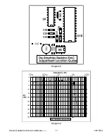
Diagram 4
7.4 SRAM Supply
SRAM Supply adjustment (See diagrams 4 and 5). This
supplies a solid 5V to the SRAM, preventing input data from
being higher in amplitude than the supply voltage, which can
cause data corruption.
Alesis QuadraVerb Service Manual------
7
08/13/04
7.5 Battery Ground
Check battery GND connection and resolder
if necessary. Cold solder joints, can exist there,
resulting in memory loss and crashing.
Diagram 5
7.6 Cables
Check all connector cables are firmly seated. In some cases, they can come 1/2 way off.
7.5 LCD Contrast
Check LCD contrast - if contrast is too dark then short D6.
7.6 LCD Cable Header
Hot glue the LCD cable header to LCD, to prevent it from falling off in transit.
7.7 Wet VCA Removal
A-E Software version 1.07 or above
It may be necessary to bypass the wet VCA to
decrease the noise floor. To do this, remove U6. Add jumpers across C11, C12, from U6 pin 1 to pin
3, and from pin 5 to pin 7 (see diagram 7).*
Summary of Contents for QUADRAVERB
Page 16: ...Diagram 7 Alesis QuadraVerb Service Manual 10 08 13 04 ...
Page 17: ...Diagram 8 Diagram 9 Alesis QuadraVerb Service Manual 11 08 13 04 ...
Page 20: ...9 0 Schematics Alesis QuadraVerb Service Manual 14 08 13 04 ...
Page 21: ...Alesis QuadraVerb Service Manual 15 08 13 04 ...
Page 46: ...NOTES Alesis QuadraVerb Service Manual 40 08 13 04 ...


